Killer Whale
Killer Whale keyboard is a split keyboard with a unique and versatile thumb cluster, created by Taro Hayashi.
Main features:
- 48-56 keys (4 key thumb cluster on each side)
- 30 degree tilt
- trackball, d-pad or joystick thumb cluster on each side
- built in scroll wheel and toggle switch on each side
- modular build - thumb clusters can be swapped for others (or removed altogether)
In addition to these functional features, Killer Whale offers a unique look with acrylic (or printed) pillars that structurally support the different parts of the keyboard.
Killer Whale is also sold on Yushakobo, a popular Japanese marketplace. The version brought by holykeebs brings a few "quality of life" improvements that make the build easier (detailed below), without sacrificing the tenets that make this keyboard awesome.
Buyer's Guide
Killer Whale is comprised of 3 distinct sections (per half):
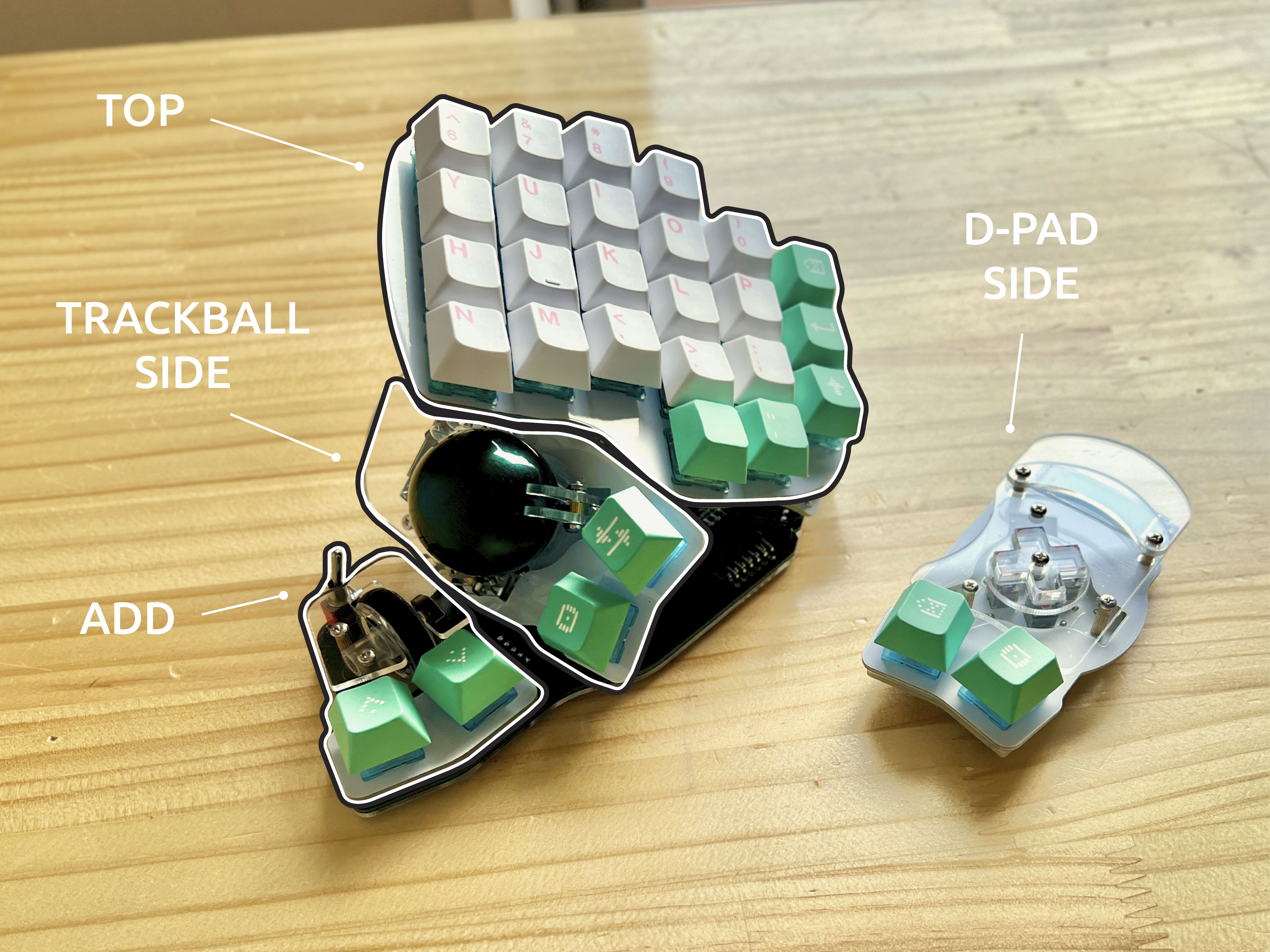
- TOP: main typing area, tilted 30 degrees, 26 keys with per key LEDs
- SIDE: thumb cluster with 2 keys that can be either a trackball, a joystick, or a 4 key gamepad style D-pad
- ADD: an additional thumb cluster with 2 keys, a scroll wheel, and a toggle switch
With these extra parts, the keyboard uses more components and fasteners compared to a "regular" DIY split keyboard like a Corne or a Lily58.
If this is your first keyboard, the general purpose Build Guide is a recommended read, even though some of the options are not relevant to Killer Whale.
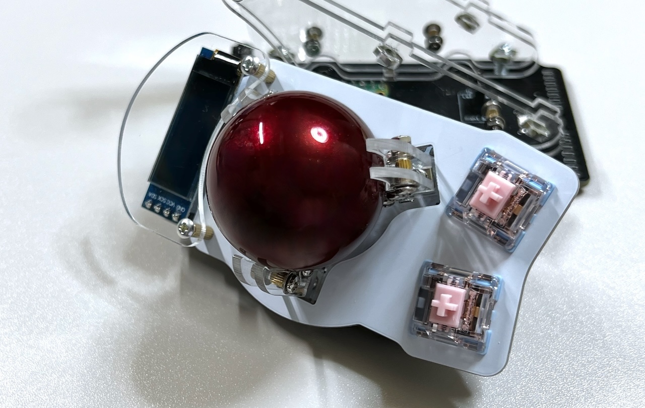
34mm Trackball
If you've chosen the trackball side unit, you'll need a 34mm trackball, which is not included in your purchase. There are many color options to choose from, and the ones made by Perixx are a popular choice.
Build Service
Similar to our other keyboards, we offer keyboards in kit form (no build service) or fully soldered. A fully soldered keyboard is not plug and play, and requires assembly of some mechanical parts (namely connecting the top, side and add units to the keyboard, and screwing the pillars into place). See the build guide for more information.
INFO
Currenly we cannot offer a fully assembled Killer Whale due to its size and risk of damage during shipping.
Colorway
The colorway lets you choose the colors of the various plates and mechanical parts in the keyboard:
- Support Pillars / Posts: these are one of Killer Whale's most recognizable features. They support the top and side units at a 30 degree angle, and come with two variants: acrylic (in clear or one side matte/one side glossy black), or 3d printed. Other than giving the keyboard a different look, these options differ in the amount of time it takes to build them. The acrylic variants make use of spacers, washers, nuts and screws to achieve the desired sturdiness and thickness. If you enjoy Lego or puzzles or working with small parts, this could be a fun build for you (check the build guide to get a taste). Otherwise, consider going for the printed variant, which use far less hardware to assemble, and are available in a lot of colors.
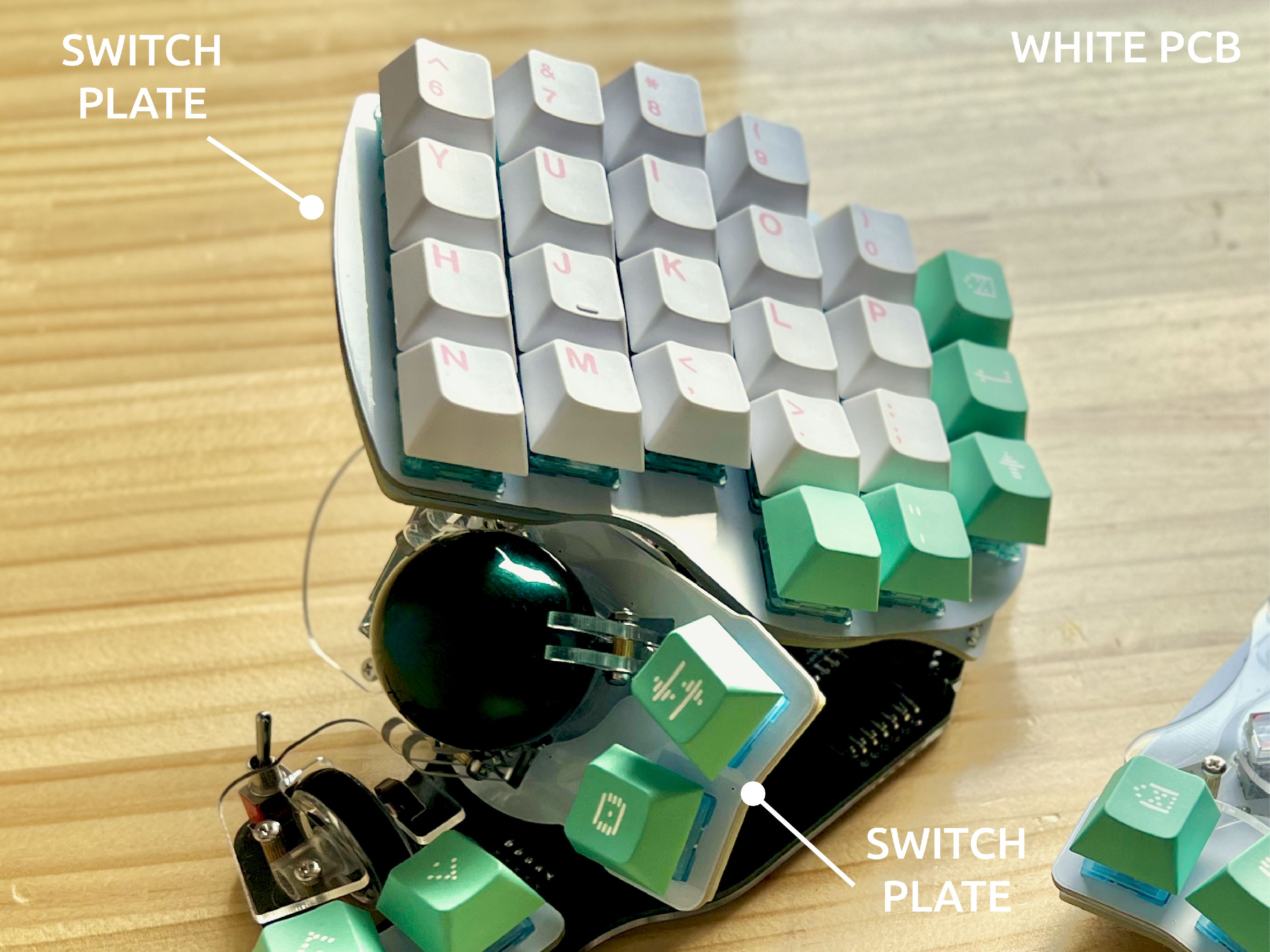
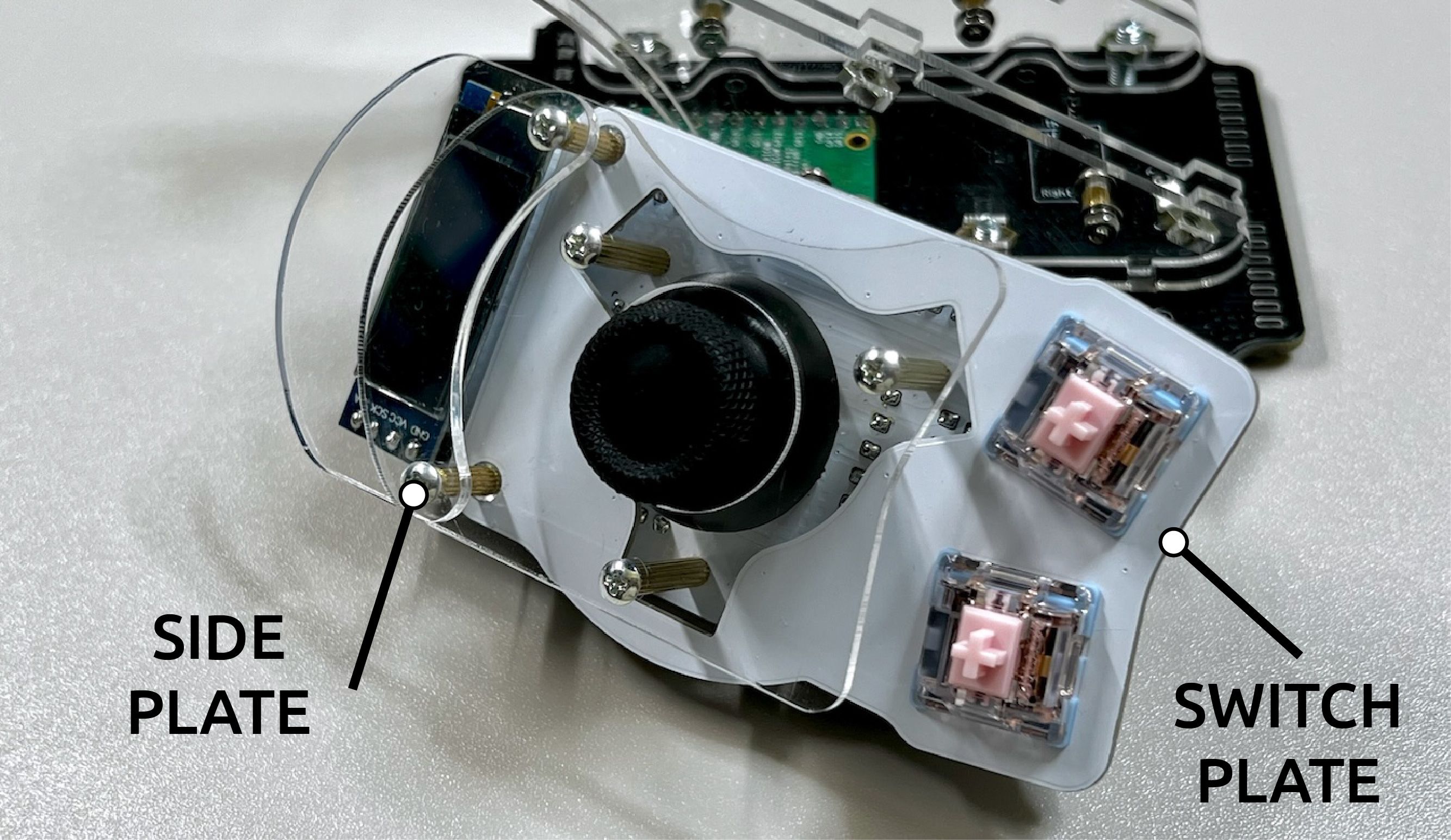
- Switch Plates: plates that switches hook into. Each section in the keyboard has one (top, side, additional). You may choose either white PCB (FR4) or 3mm acrylic in one of several colors.
- Side Plates: plates that cover the hardware and OLEDs in the side units. Comes in various acrylic colors.
- Bottom Plates: plates that cover the under side of the keyboard. Comes in various acrylic colors.
INFO
To fully customize the colors of this option, choose the Custom colorway and add this item to your cart.
Side Units
Each half of the keyboard supports one of 3 side units:
- A 34mm trackball using the high resolution PMW3360 sensor.
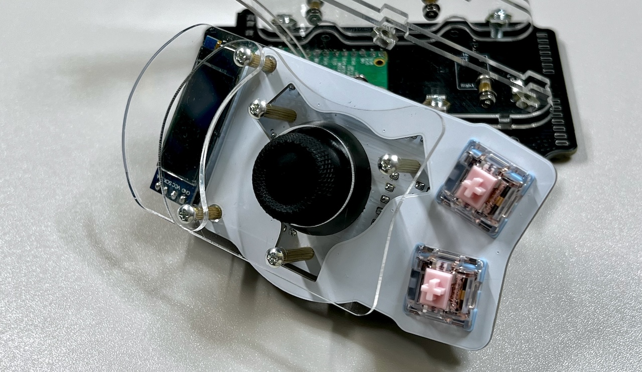
- An analog joystick that can function as a mouse or for gaming.
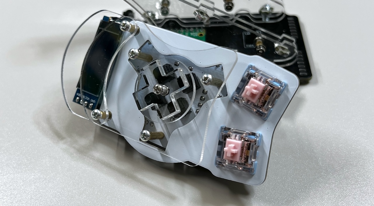
- A game pad style d-pad with 4 up/down/left/right micro buttons.
All side units have 2 thumb keys and are not specific to the left or right side of the keyboard. They can be moved around based on what feels comfortable to you.
INFO
To fully customize the colors of this option, choose the Custom colorway and add this item to your cart.
OLED
A small 128x32 OLED display that sits on the side units. These displays come preprogrammed to display keyboard information such as current layer, mouse mode, etc.
Build Guide
The build is covered in the official Killer Whale github repository: https://github.com/Taro-Hayashi/KillerWhale/blob/main/README_EN.md.
Covered here are some general tips and commentary on the build, with specific instructions on parts we've changed to improve the build process.
INFO
If you purchased a soldered version, much of the guide below can be skipped. It's still recommended to go through it to gain an understanding how the keyboard comes together given its uniqueness.
Before doing the final assembly, it's recommended to do an operation check by connecting the PCBs together and seeing everything works correctly.
Introduction
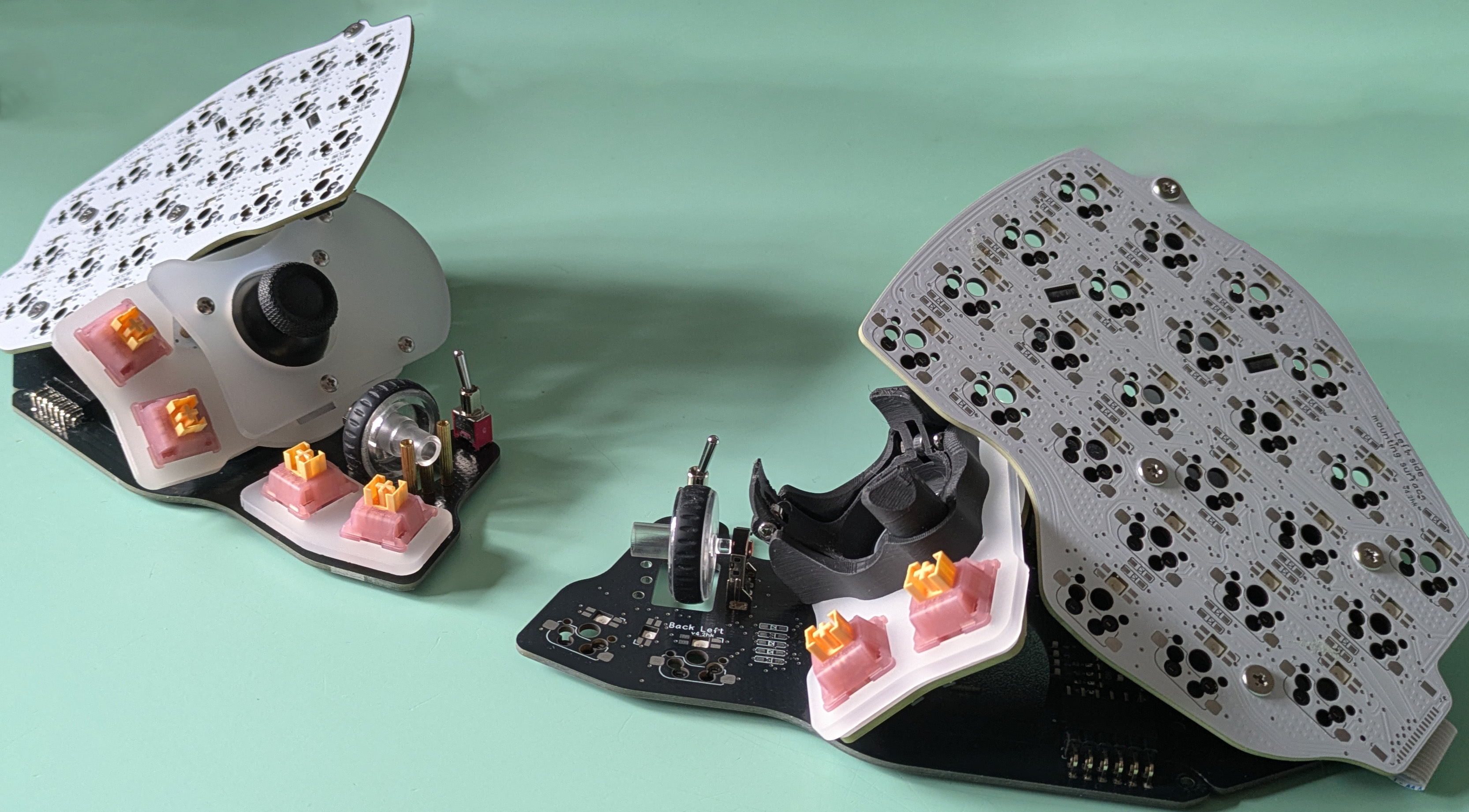
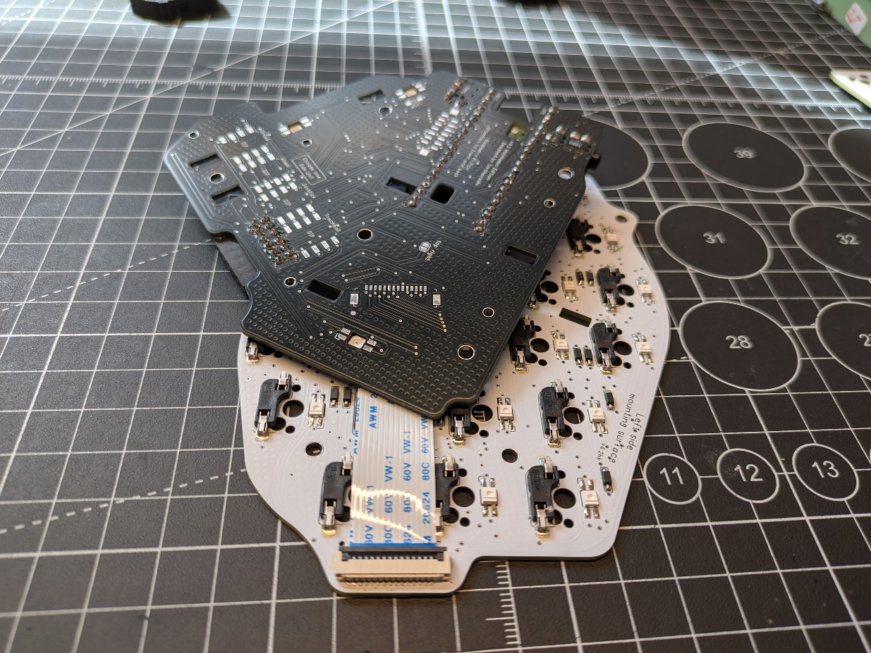
The keyboard can be thought of as having 3 sections (per half), illustrated below:
The TOP, SIDE and ADD sections all connect to the BASE, which is the black PCB sitting on the table. As these sections are all positioned at an angle relative to BASE, there are connection points between them. An added benefit is that the SIDE units can be moved between the left and right sides to your liking.
One thing you'll notice when going over the Killer Whale guide is that we've made a few changes to the official kit, these are detailed below.
We believe this makes the build easier and much less time consuming. Please read through the information below and use it alongside the official guide to build your keyboard.
SMD Components
The PCBs now use SMD components where possible: diodes, resistors, capacitors, etc. These are used the same way as the equivalent through-hole components.
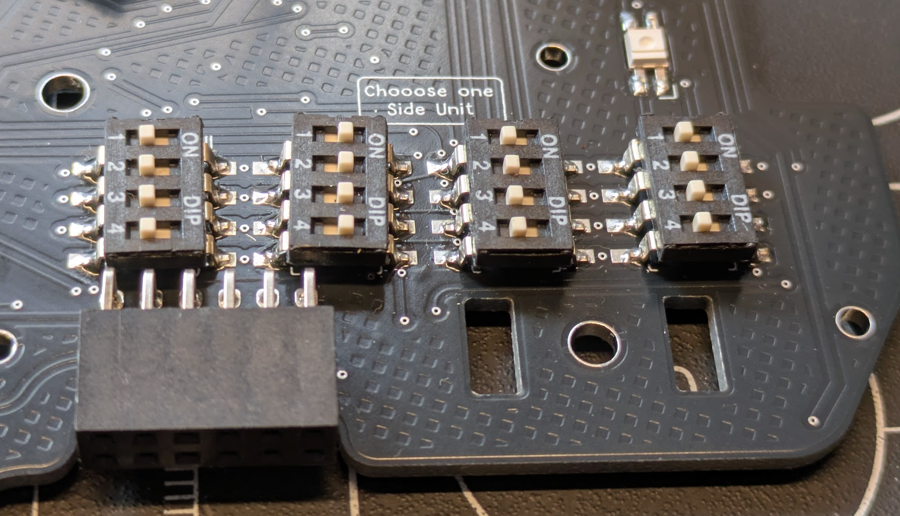
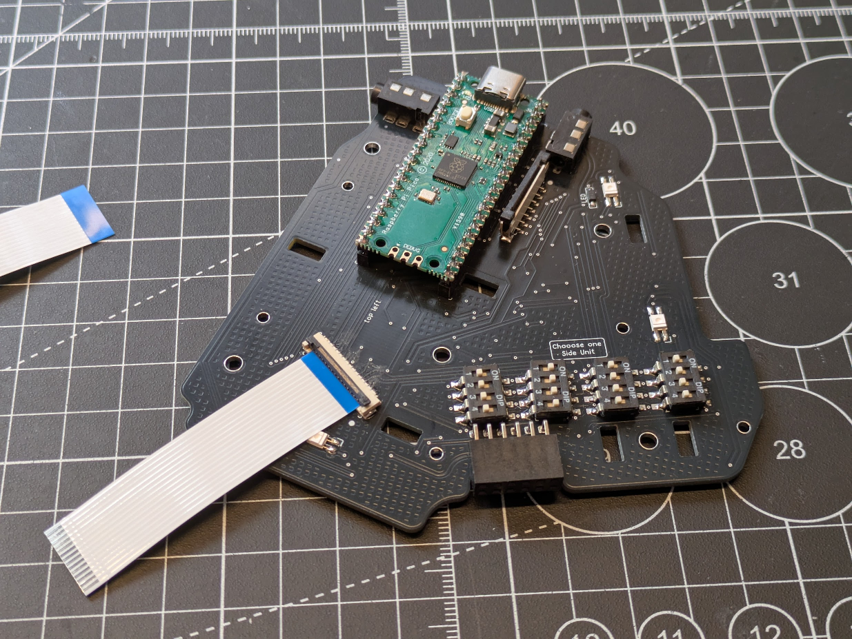
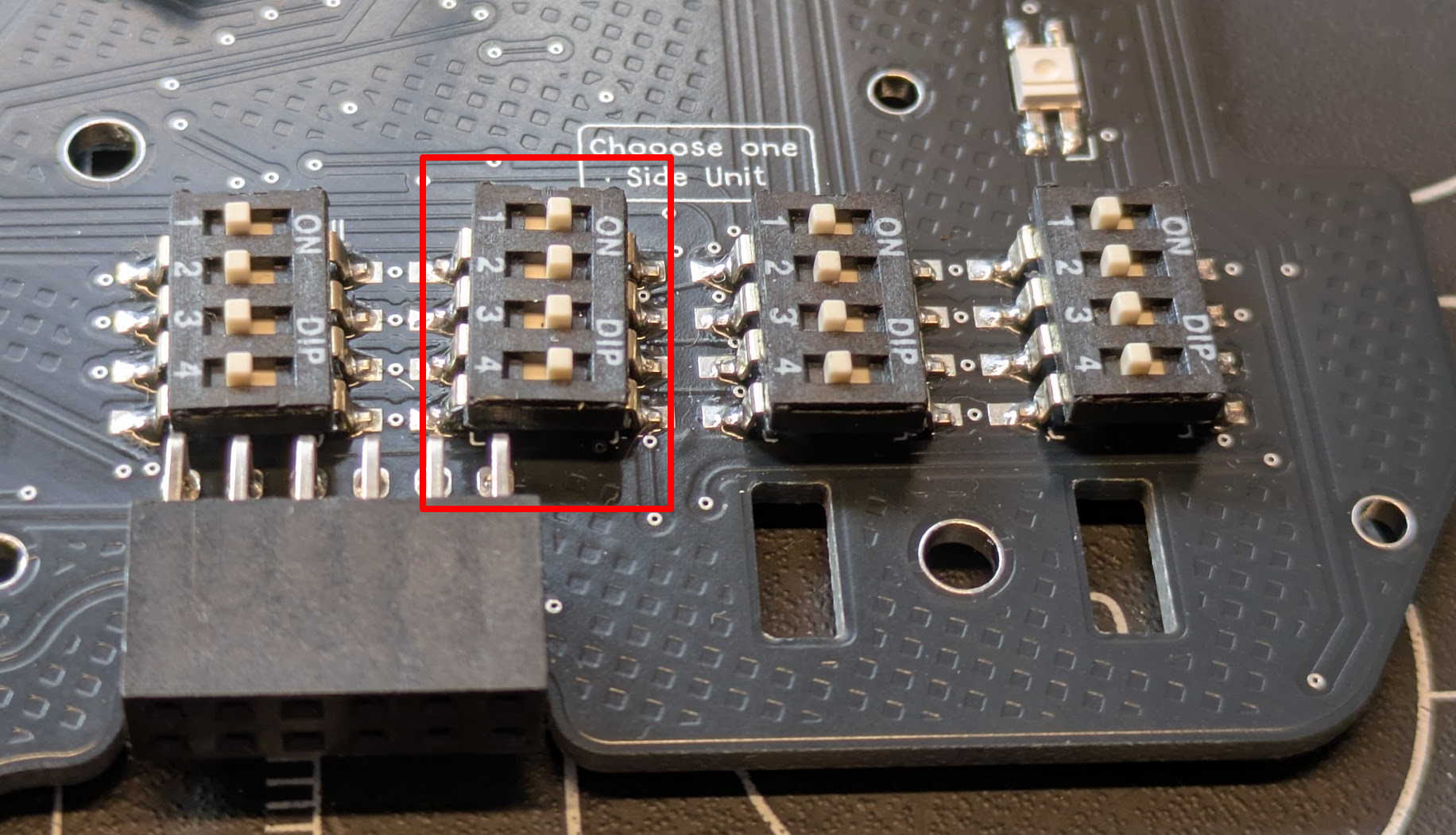
The DIP switches can be soldered in either direction, but it's nice to have them all aligned the same. Shown below, the 2nd from the left is active.
FFC Connectors
The connectors are used to connect the TOP and SIDE PCBs to BASE. You'll find two types: vertical (for BASE-SIDE) and horizontal (for BASE-TOP). Each pairing uses a 60mm reverse side FFC cable.
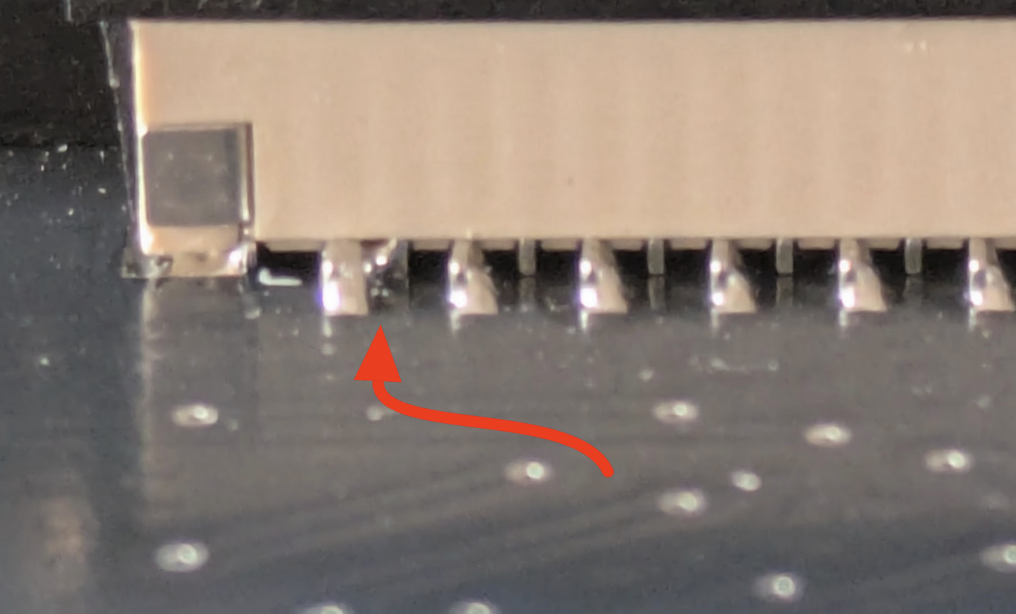
Soldering the connectors is straight forward: align with the pads on the PCB, and align the vertical one such that the contacts side is on the same side as the black dot on the PCB.
WARNING
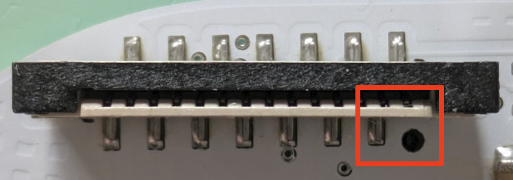
Both connectors are prone to bridging, so watch out for those (use your phone camera zoom) and fix as needed.
Here's an example of an easy to miss short in a vertical connector:
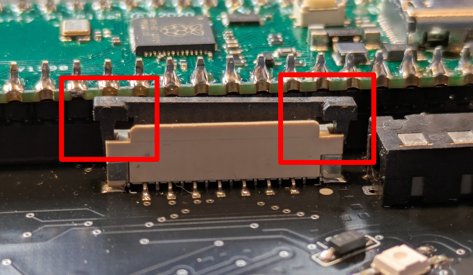
The connectors should be opened in order to insert the cables. The vertical one opens by lifting the sides:
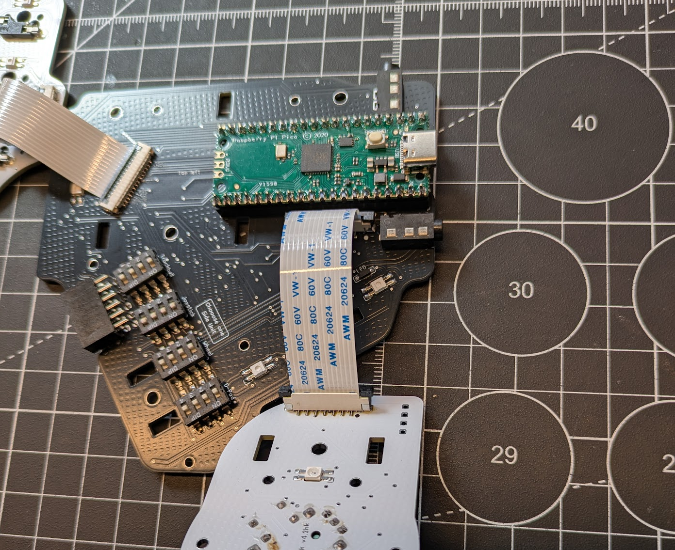
Connect the units together as shown below:
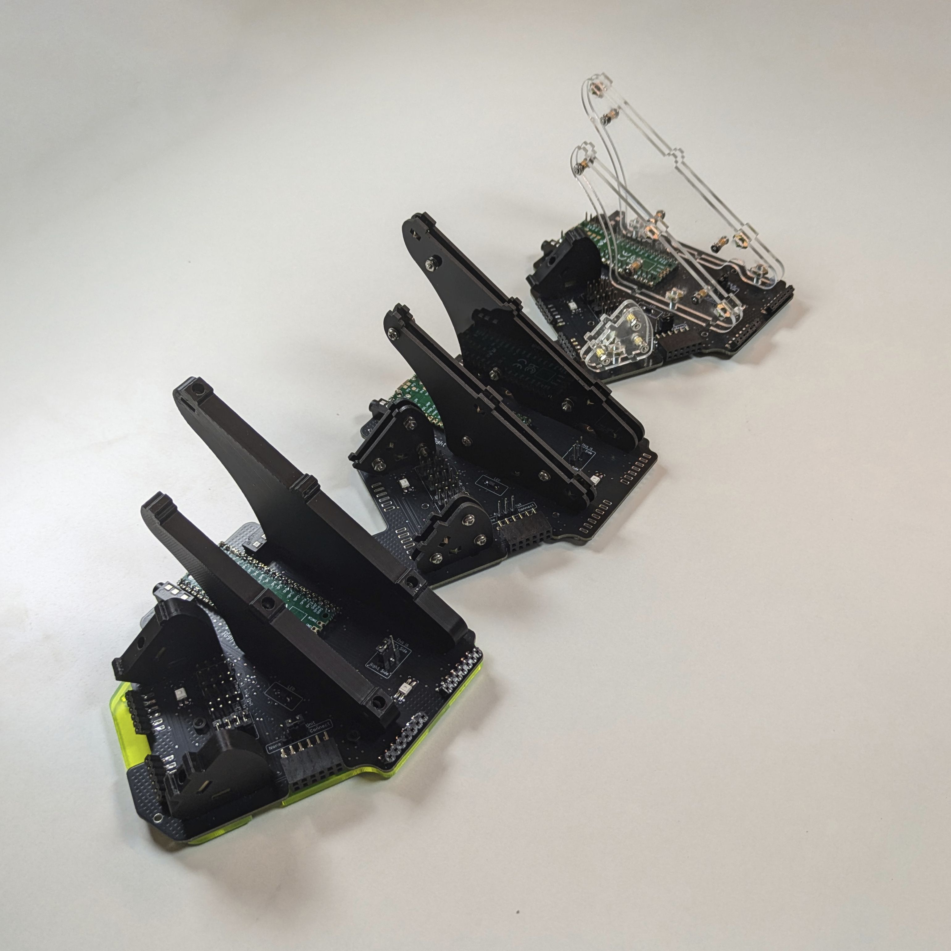
Support Pillars
In order to position the TOP and SIDE units (and trackball), the keyboard uses a clever support structure design (also called posts or pillars). There are two variants:
acrylic: these are built using 2mm plates that are spaced out using 3mm standoffs, combined to a thickness of 7mm. Assembling the acrylic posts is rather time consuming and repetitve as it involves many screws, nuts, washers and spacers. The black acrylic posts come one matte, one side glossy. You may choose which side you want facing in / out.
printed: these don't have a lengthy assembly time like the acrylic posts, only requiring the square nuts. The printed posts are made on a textured surface, so you'll notice one side is textured and smooth. You may choose which side you want facing in / out.
The official build guide uses the acrylic posts exclusively, but they're both mounted the same way on the PCBs.
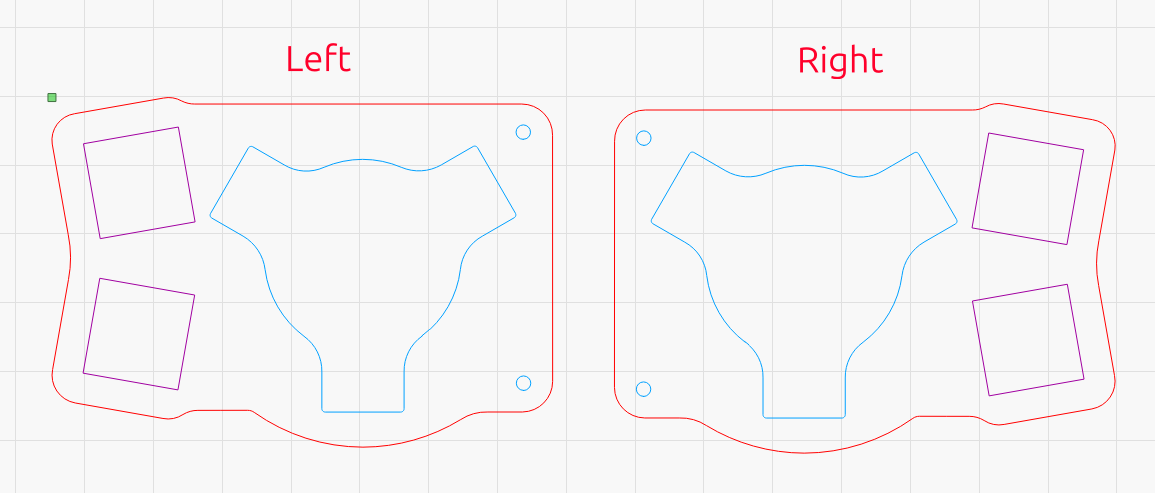
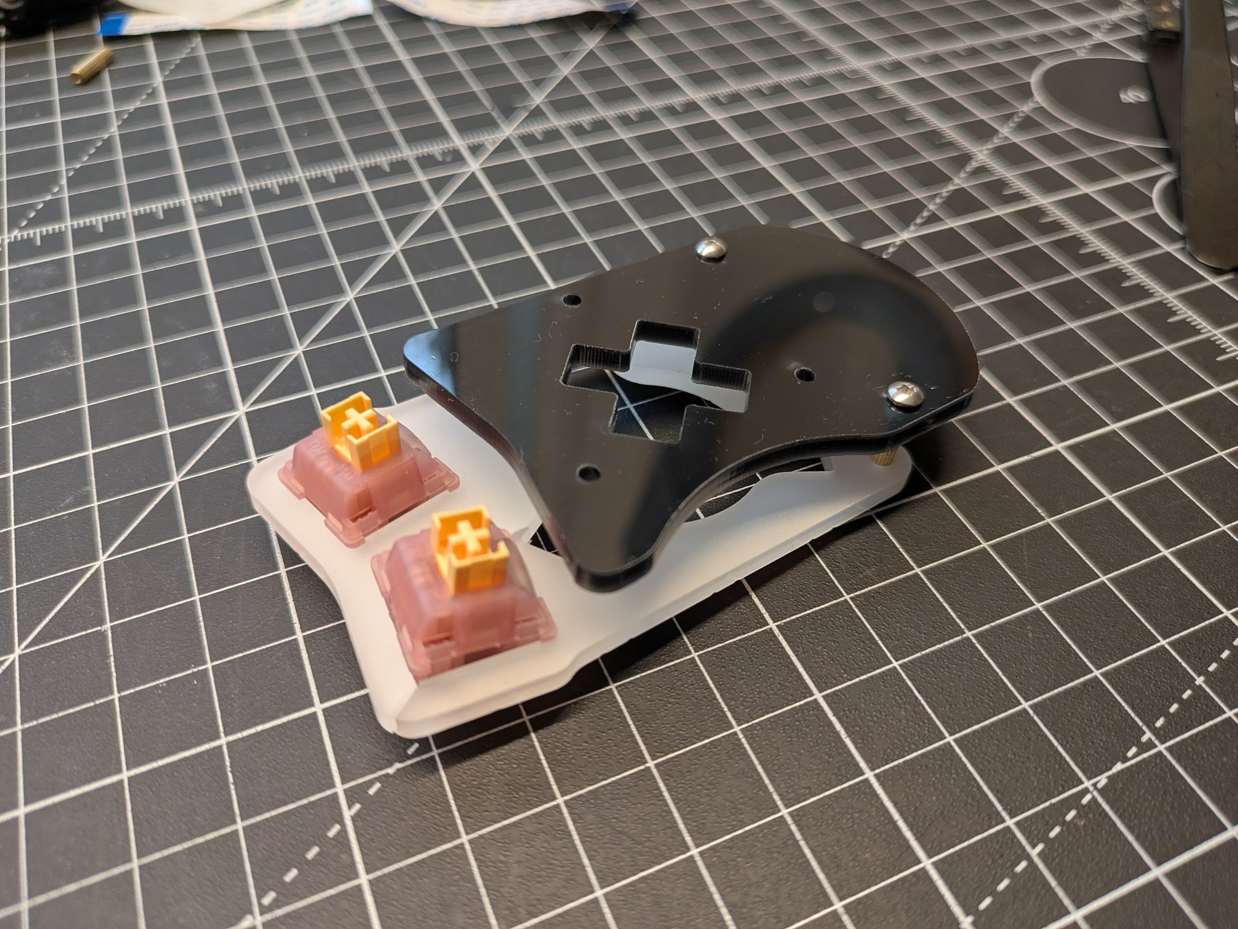
Switch Plates
If you do not have acrylic switch plates, you may skip.
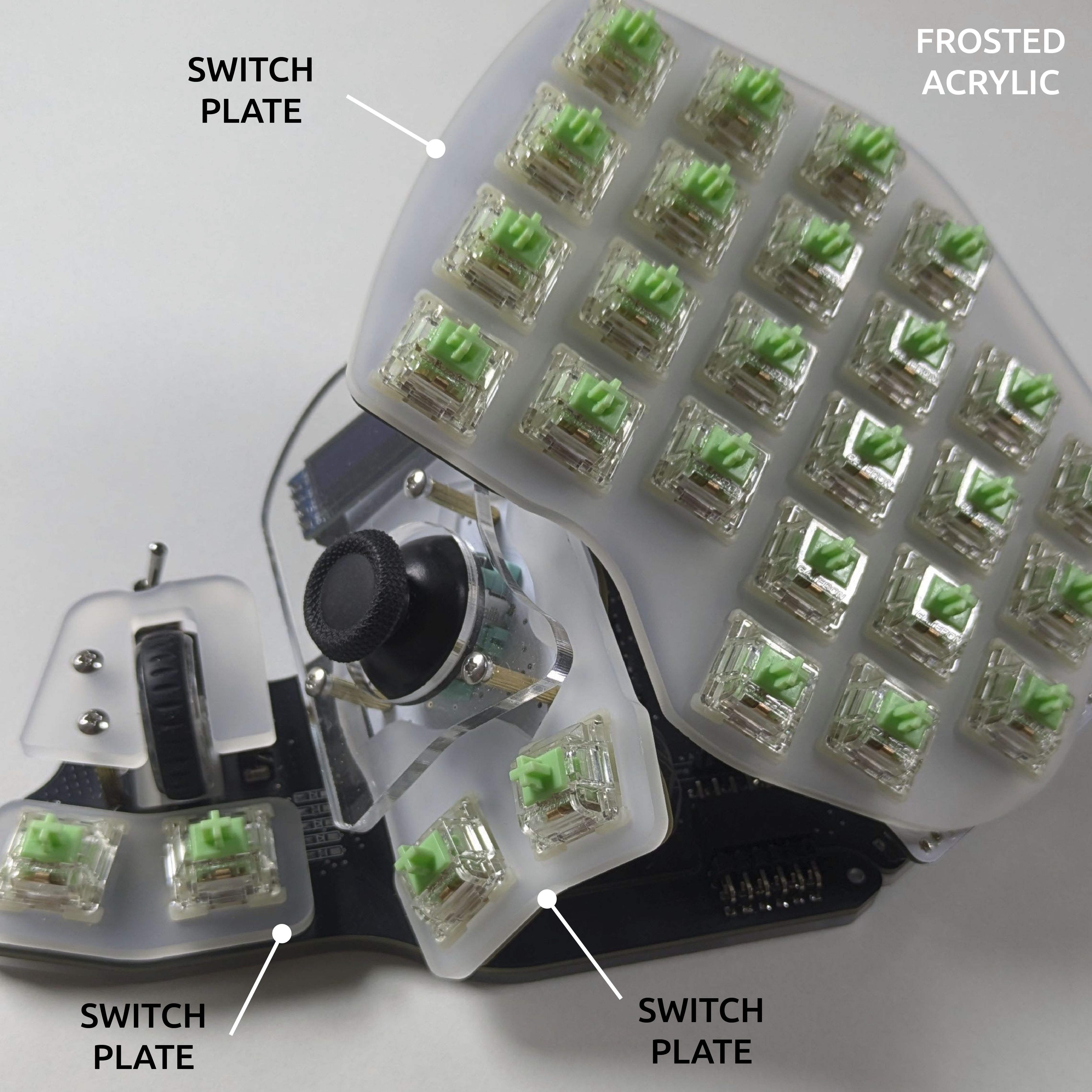
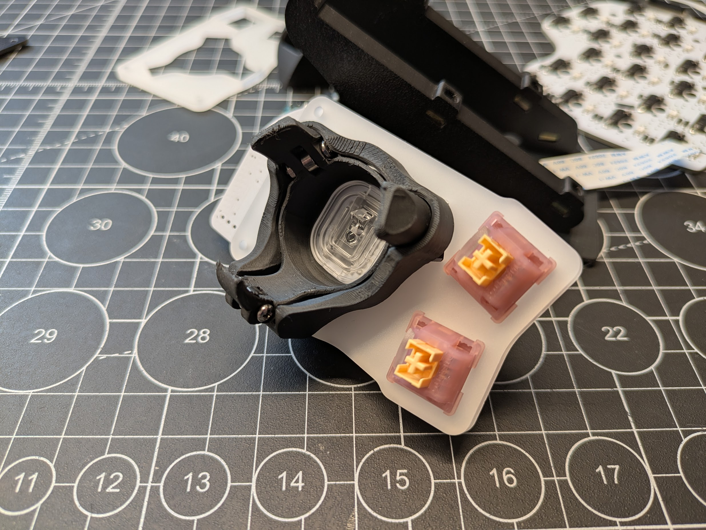
Acrylic switch plates are laser cut, and due to the nature of the laser cutting process, the size of a hole will differ on its top and bottom sides, and there might be some variance in how tight or loose the switches are held in the holes.
Your plates will arrive with one side having no protective film, and one side having one. First try pushing the switches from the side with no film. If you encounter too little or too much resistance, try pushing from the other side. Regardless, the switches will be secure once pushed into the hotswap sockets.
WARNING
Acrylic can be fragile in thin areas, support those areas when pushing the switches in.
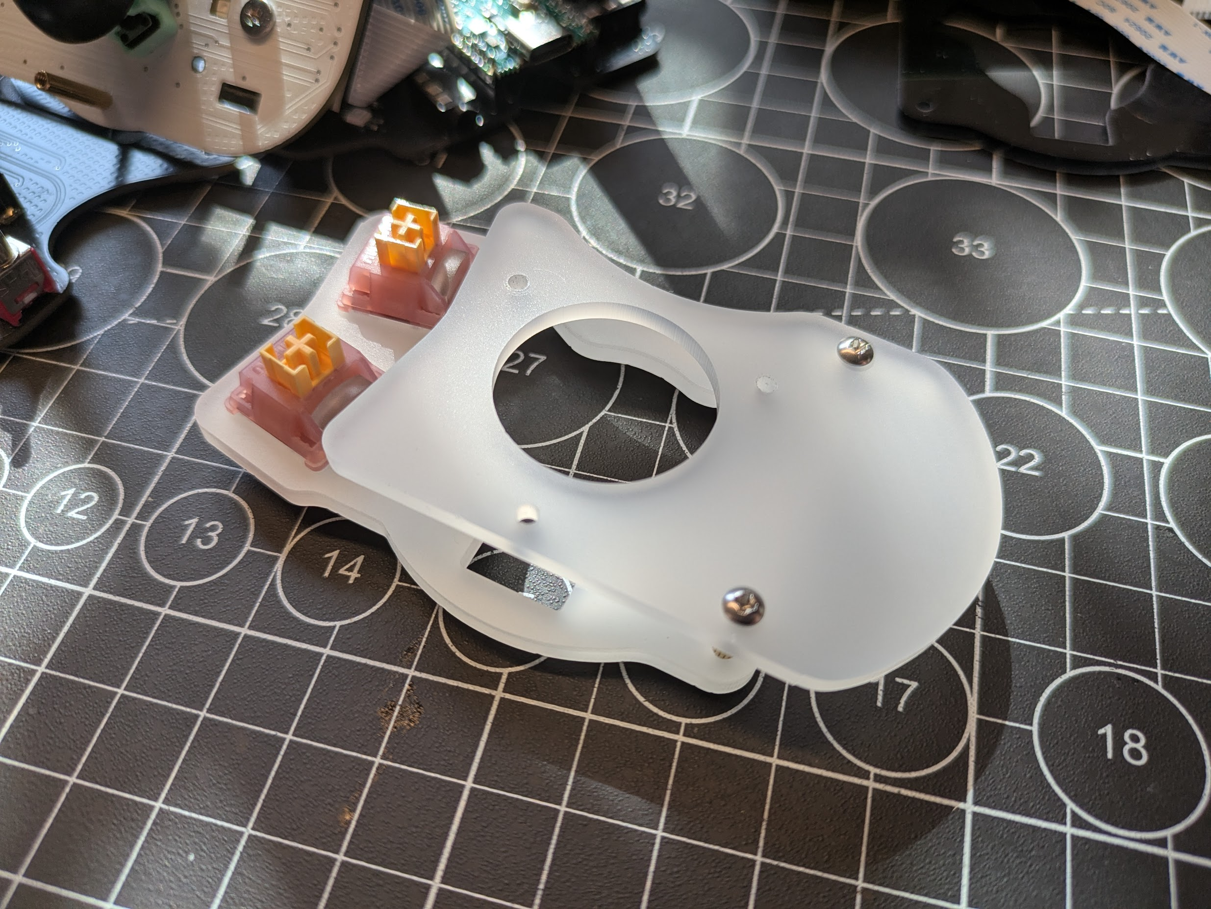
The side unit switch plates have an orientation and should be used like so (with the no film side on top):
OLED Cover
The OLED cover for the joystick and d-pad sides is now part of the main acrylic piece, rather than being separate.
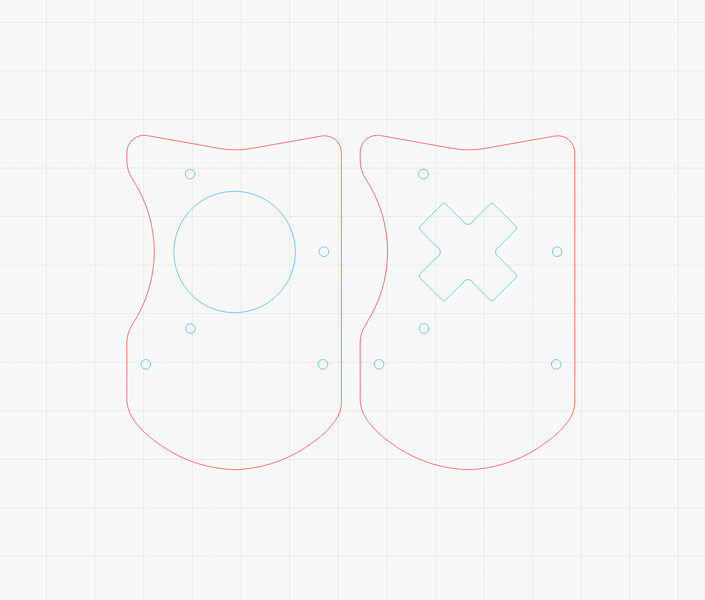
Trackball Holder
The trackball holder has been updated to a more robust design that holds the ball better.
If you'd like to print your own, find the files here: 1 x cover + 1 x holder for PCB plate or 1 x holder for acrylic.
BASE
The base unit is brains of the keyboard, has the Pi Pico controller and where all the sections connect to. The picos arrive with precut 20P headers and sockets. It's highly recommended to use the sockets.
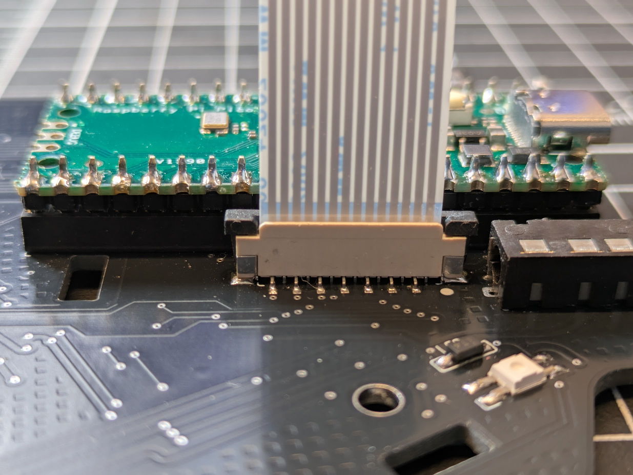
WARNING
The headers don't push in all the way into the sockets. This is as far as they'll go:
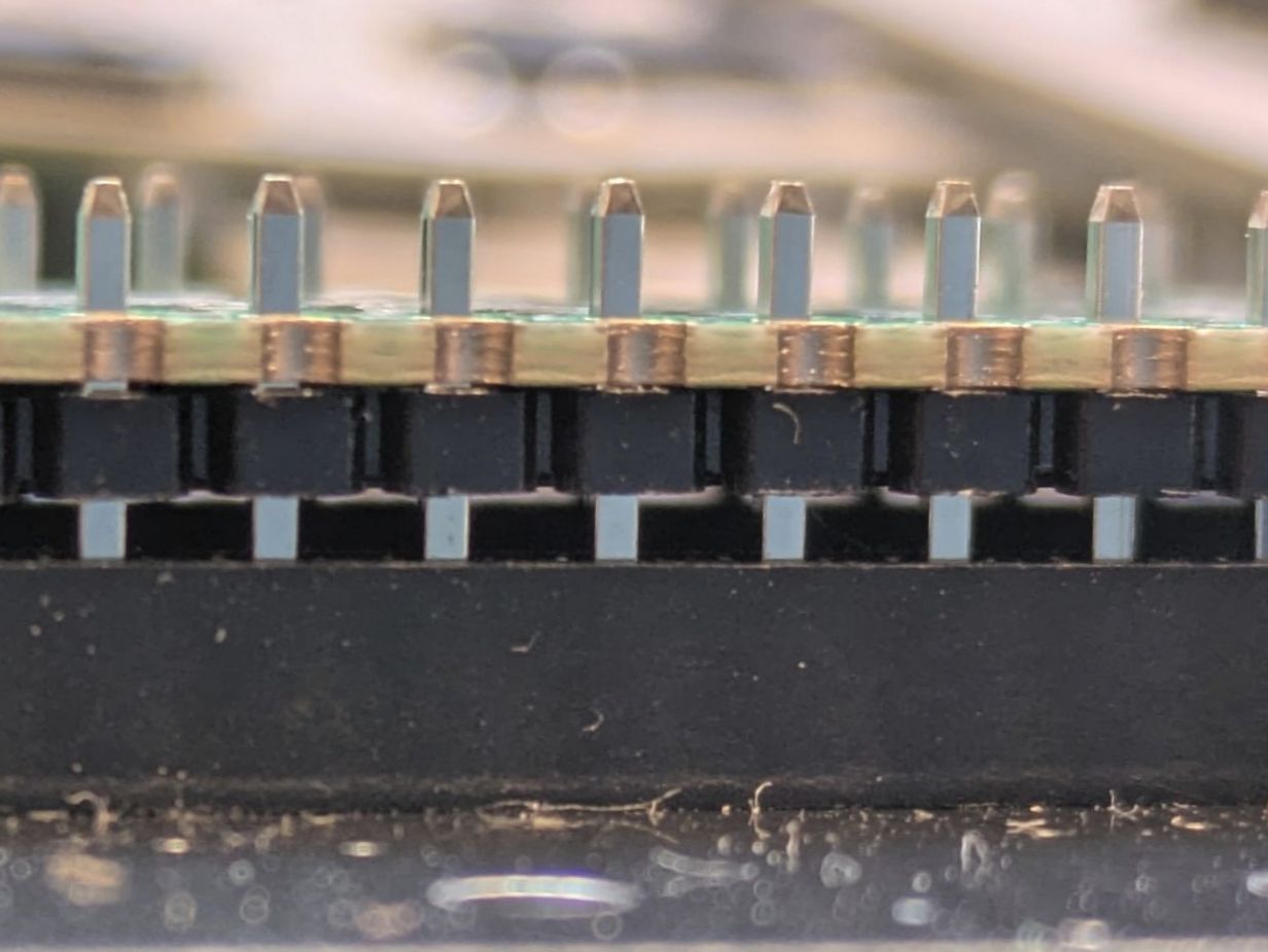
Pushing the headers into the sockets takes a bit of force due to their length and tight tolerances.
If soldering LEDs, only a diode is required in the area labeled LED on the PCB.
Solder the FFC connectors. Do this before soldering the controller!
If your kit came with printed posts, assembly is simpler: place a square nut in each post, centering its hole with the screw hole.
Continue by following the official guide (left, right).
INFO
The Pico controllers have a USB-C socket but only work with an A to C cable.
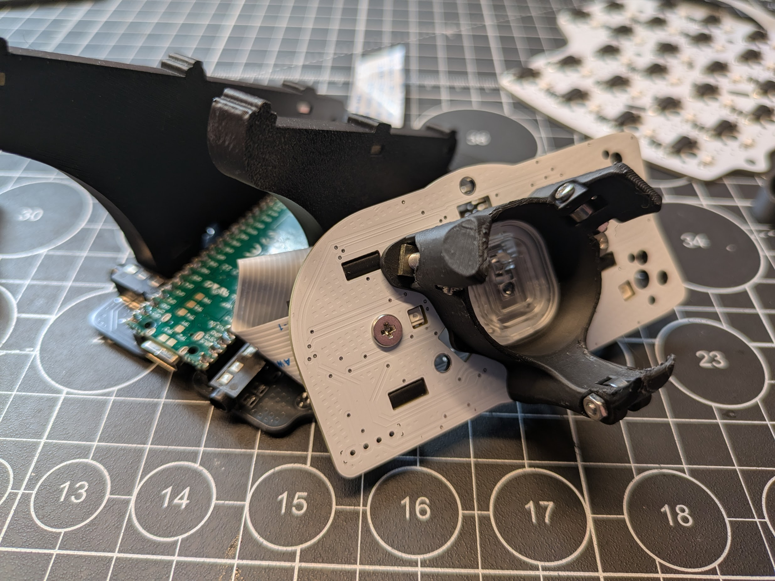
SIDE: Trackball
Follow the official guide (left, right), and take note of these things:
As mentioned before, you'll see SMD components in the trackball bag - solder them similarly to what's explained in the official guide.
Solder the vertical FFC connector.
The trackball holder has been updated to a more robust design that holds the ball better. Screw the 3 bearings with M2x10mm screws:
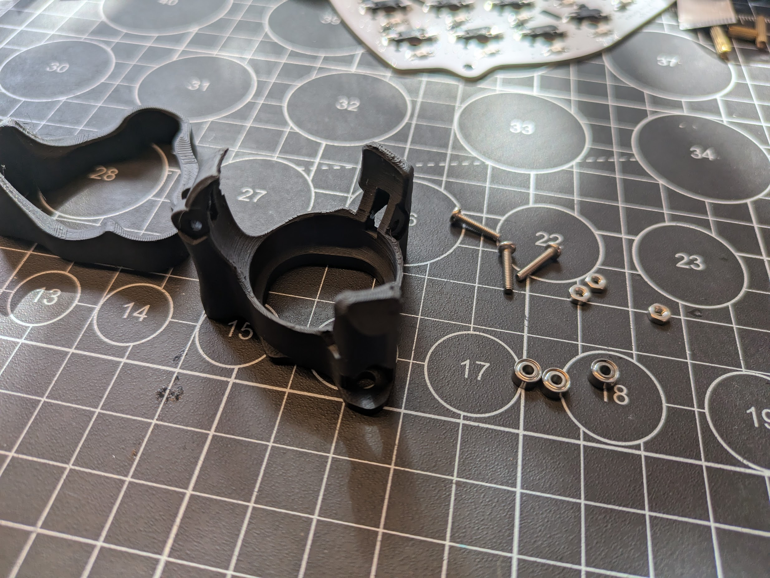
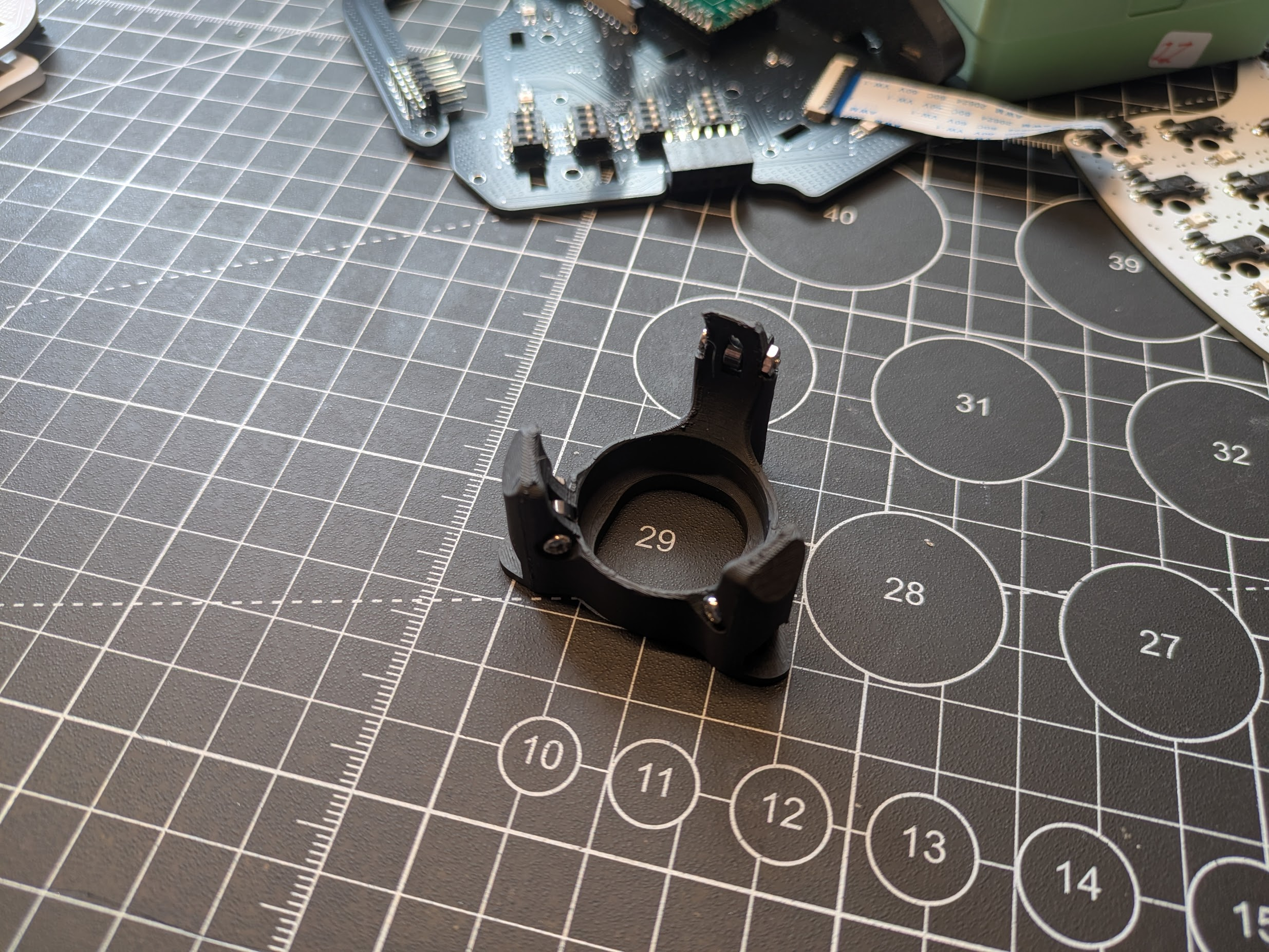
Mount the holder onto the PCB (notice the orientation, it matters) with M3 screws and square nuts. The holder cover goes on top of the switch plate.
SIDE: D-Pad
Follow the official guide (left, right), and take note of these things:
As mentioned before, you'll see SMD components in the d-pad bag - solder them similarly to what's explained in the official guide.
Solder the vertical FFC connector.
SIDE: Joystick
Follow the official guide (left, right), and take note of these things:
As mentioned before, you'll see SMD components in the d-pad bag - solder them similarly to what's explained in the official guide.
Solder the vertical FFC connector.

TOP Unit
Follow the official guide (left, right), and take note of these things:
Solder the horizontal FFC connector.
If you chose acrylic switch plates, you'll find M3 screws with a flatter head than the rest of the M3 screws in the kit. Use these for fixturing the PCB to the pillars.
When pushing switches into the switch plate, insert a couple around the edges and then push it gently into the PCB. You should have a gap between the switch plate and the PCB. Once the two are fixed together, start adding more switches, while maintaining the gap.
WARNING
When pushing switches into the sockets, don't use brute force as it may damage the PCB. If you encounter unusual resistance, check for bent pins on the switch, or whether the switch orientation is correct, or other things that may look wrong.
ADD Unit
Follow the official guide (left, right).
Assembly
Follow the official guide (left, right), take note of the information below:
The Pico controllers have a USB-C socket but only work with an A to C cable.
See FFC connector on how to connect the cables.
Set the DIP switch on BASE according to the SIDE unit being used. In the image below, the marked switch is the one that's "on". Above the switch (not visible in the photo, are labels that show the side unit kind this switch activates). Note that your PCB may have 3 instead of 4 total switches.
- Since the PCBs are reversible, it can be a bit confusing to know if a PCB belongs to the left or right half of the keyboard. This table shows the label you should be seeing on the top surface of a PCB to know which side it goes on:
| left | right | |
|---|---|---|
| base | top left | top right |
| top | top left / left side mounting surface | top right / right side mounting surface |
| add | top left / back right | top right / back left |
| side | n/a (pcb is non reversible) | n/a (pcb is non reversible) |