Touchpad Module
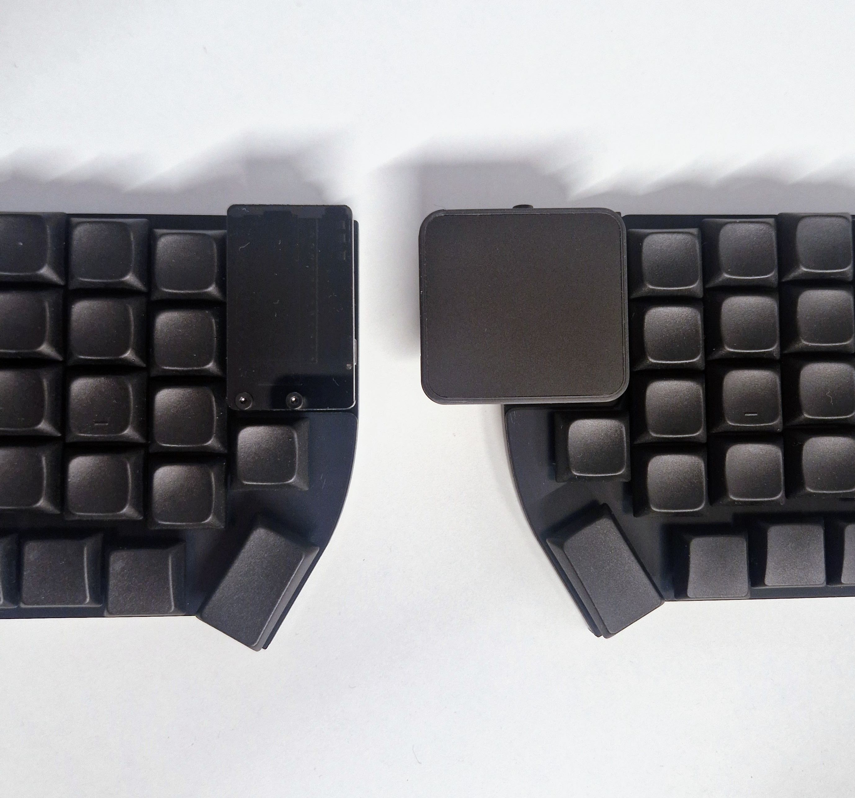
The touchpad module consists of a small adapter PCB (shield) that sits on a top mounted controller, and creates the necessary connections to easily use an Azoteq TPS43 touchpad.
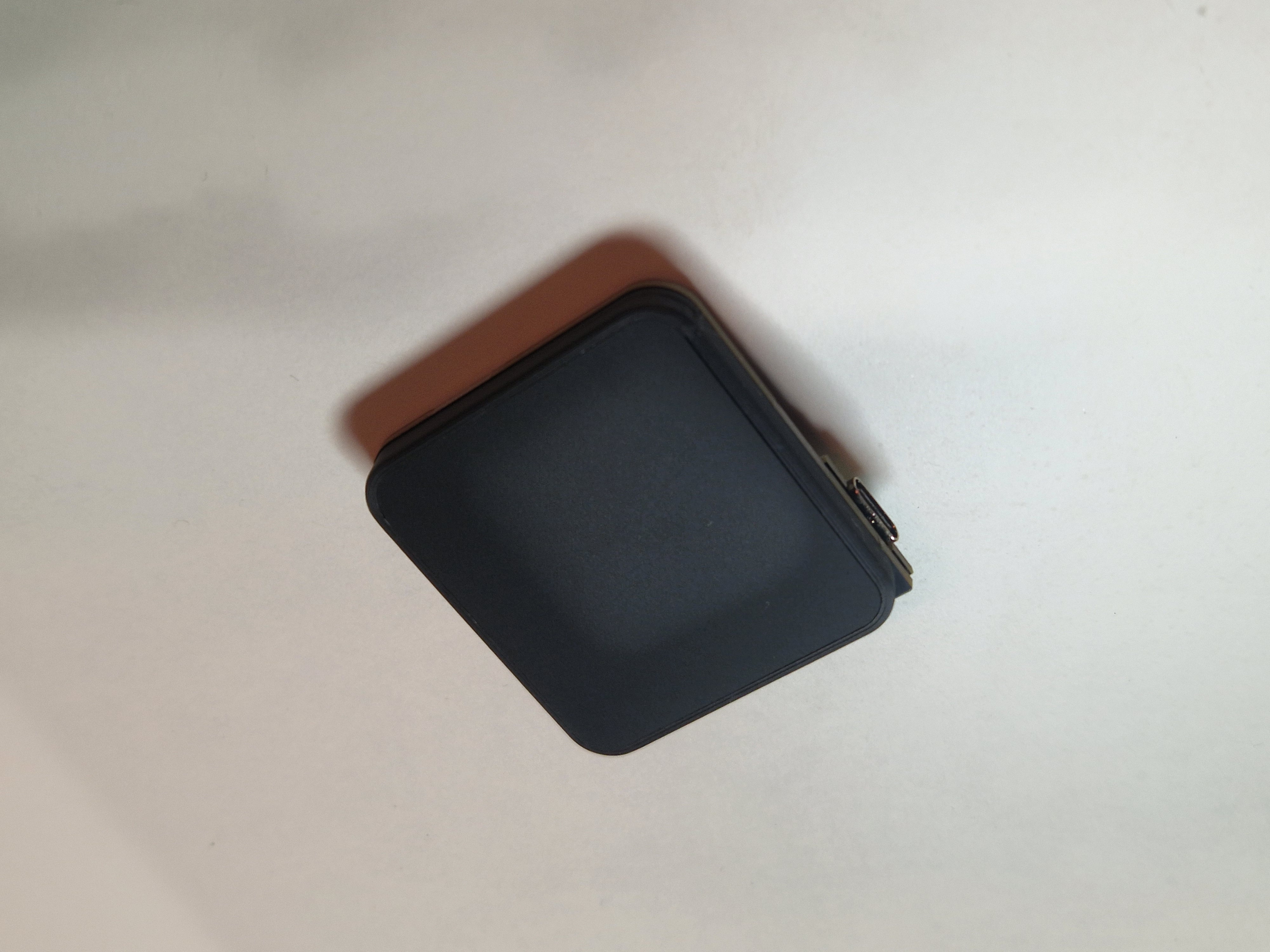
The TPS43 is a 43x40mm touchpad, supporting multitouch and gestures.
INFO
This guide has been updated to a newer, more capable touchpad. For the previous 35/40mm round touchpads, go here.
Tools
In addition to a soldering iron, you will need an H1.3 M2 hex key. Parallel pliers can help with pushing the acrylic cover into the mount.
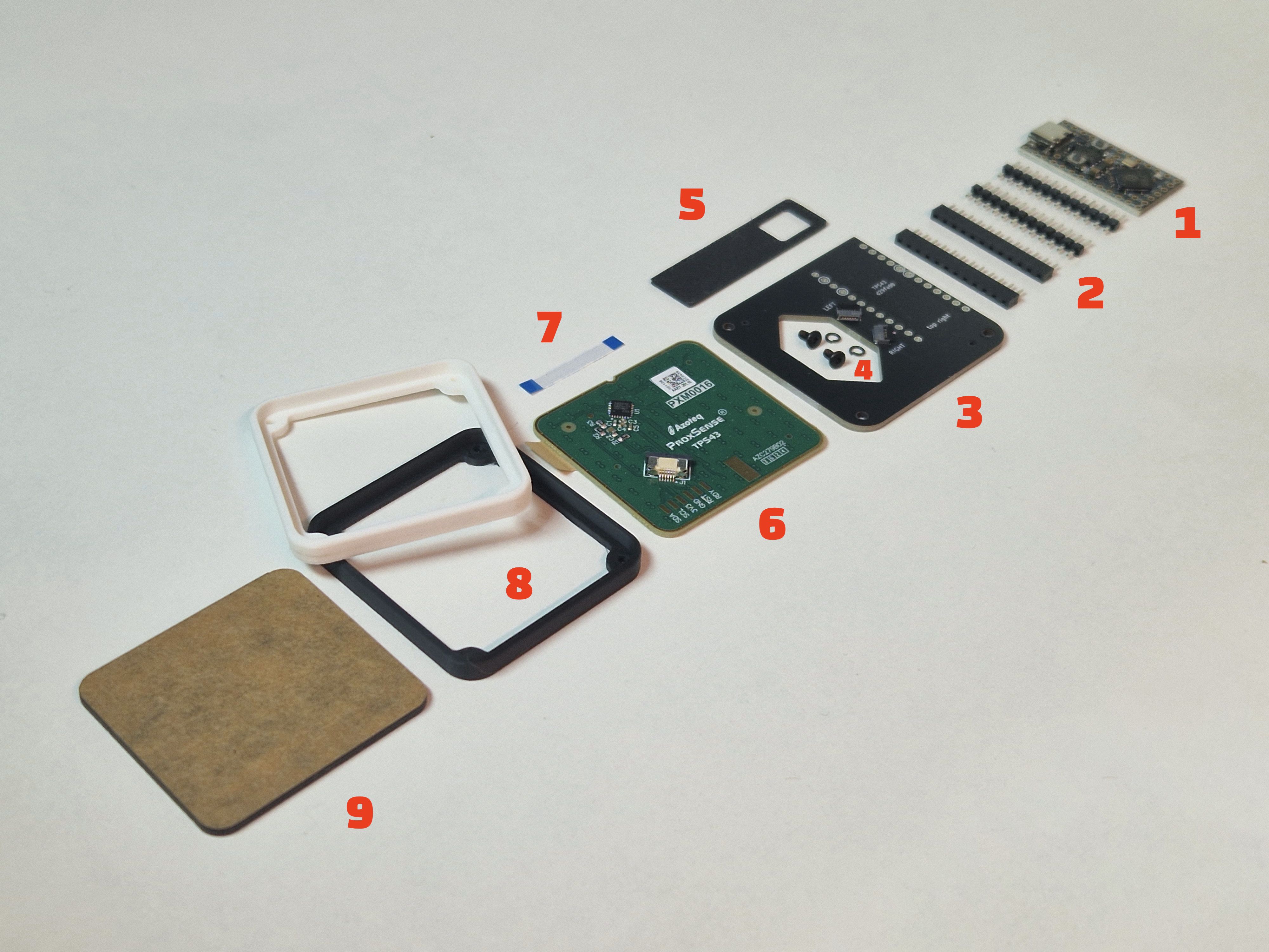
BOM
| description | quantity | |
|---|---|---|
| 1 | RP2040 controller | 1 |
| 2 | Custom low profile sockets | 2 |
| 3 | adapter PCB | 1 |
| 4 | M2x4mm screw, spring washer | 2 |
| 5 | 1mm spacer | 1 |
| 6 | TPS43-201A-B | 1 |
| 7 | 6-pin, 0.5 pitch FFC cable | 1 |
| 8 | 3d printed mount | 1 |
Soldering
Step 1
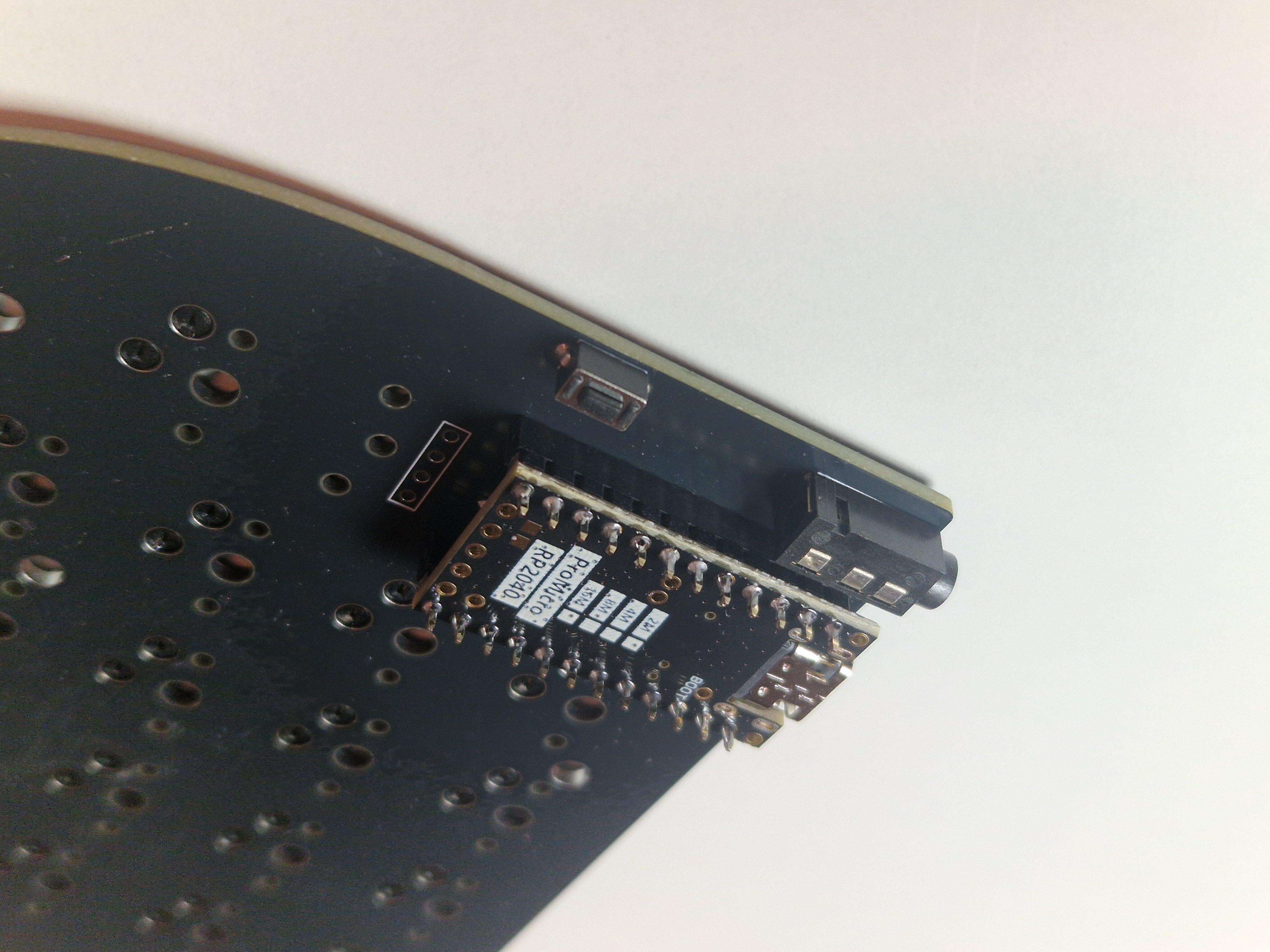
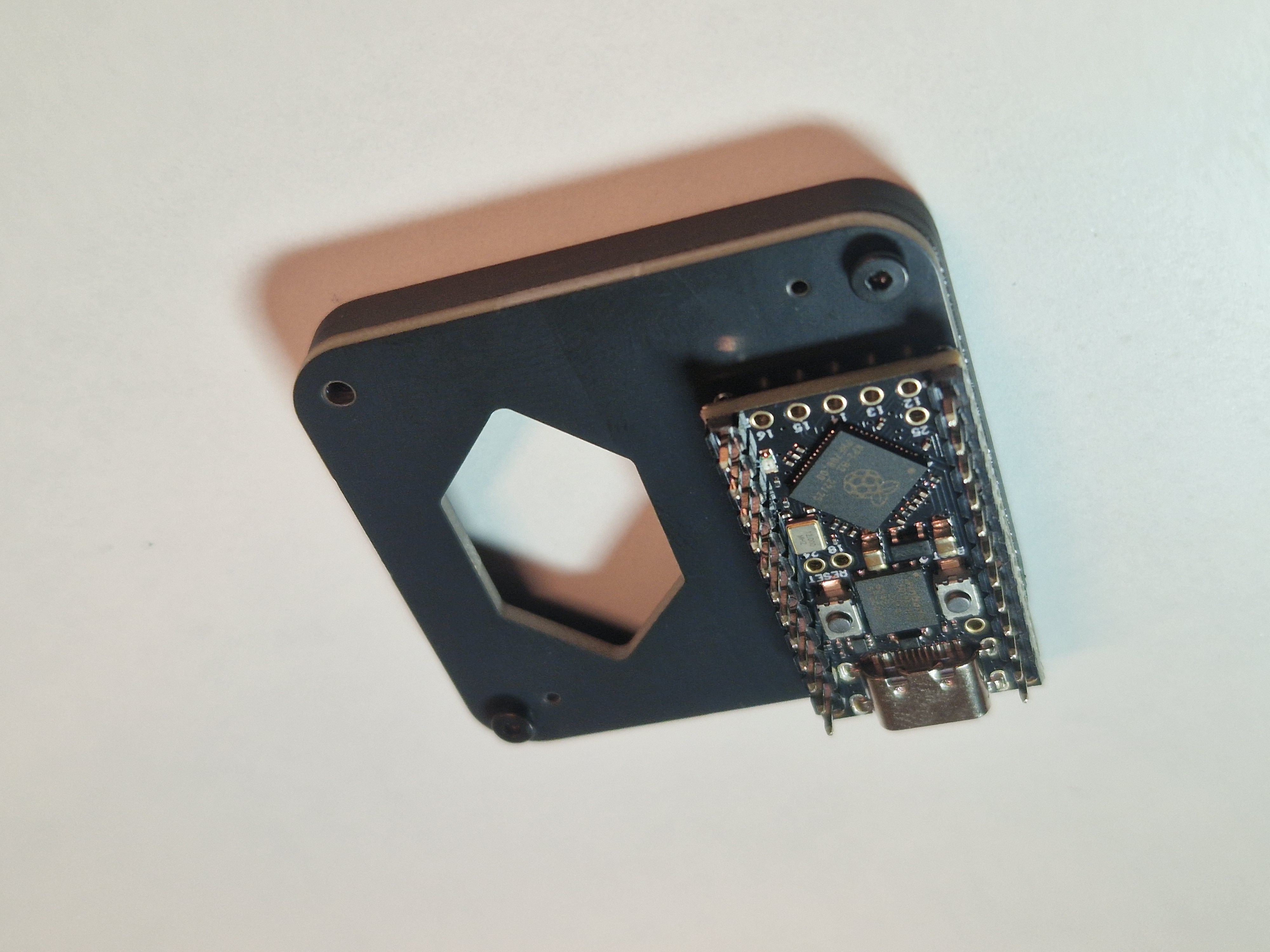
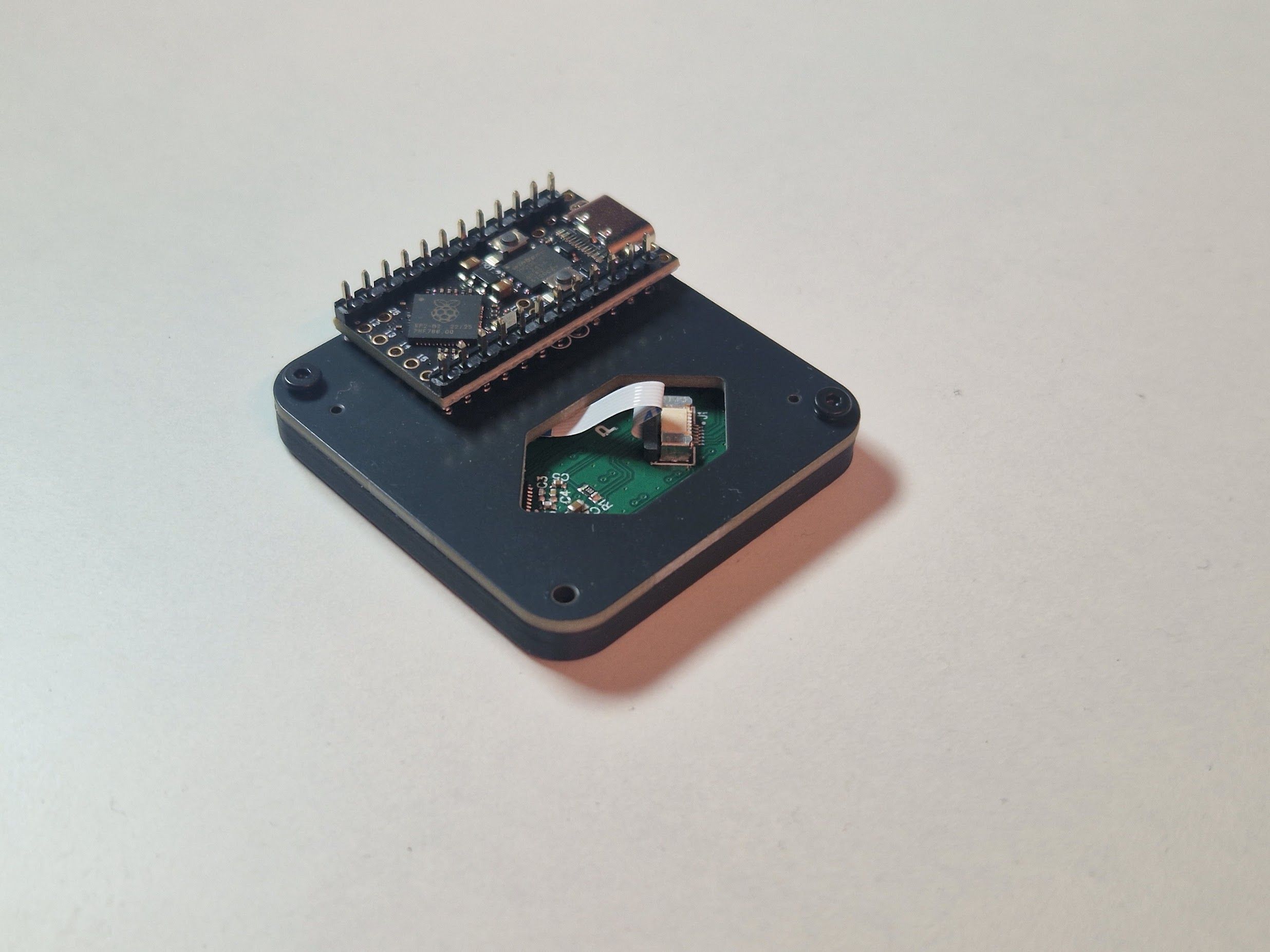
First, we need a soldered controller to mount the touchpad on. Wether you got one in your kit, or you're bringing your own, solder it. See the Controllers section in the general keyboard build guide for soldering tips.
WARNING
Take note that you're soldering the correct pins on the controller: each column should have an unsoldered pin near the USB connector!
Step 2
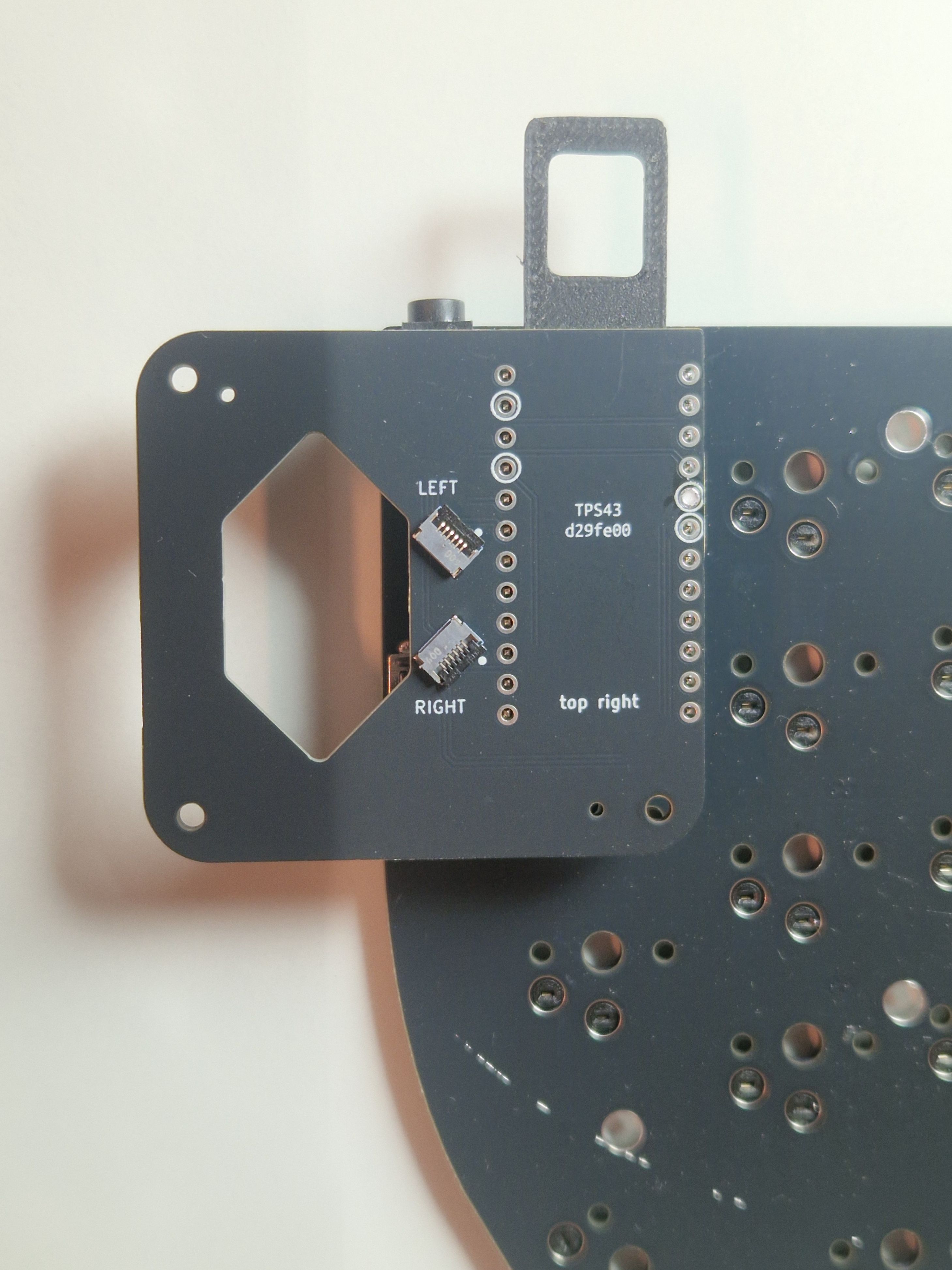
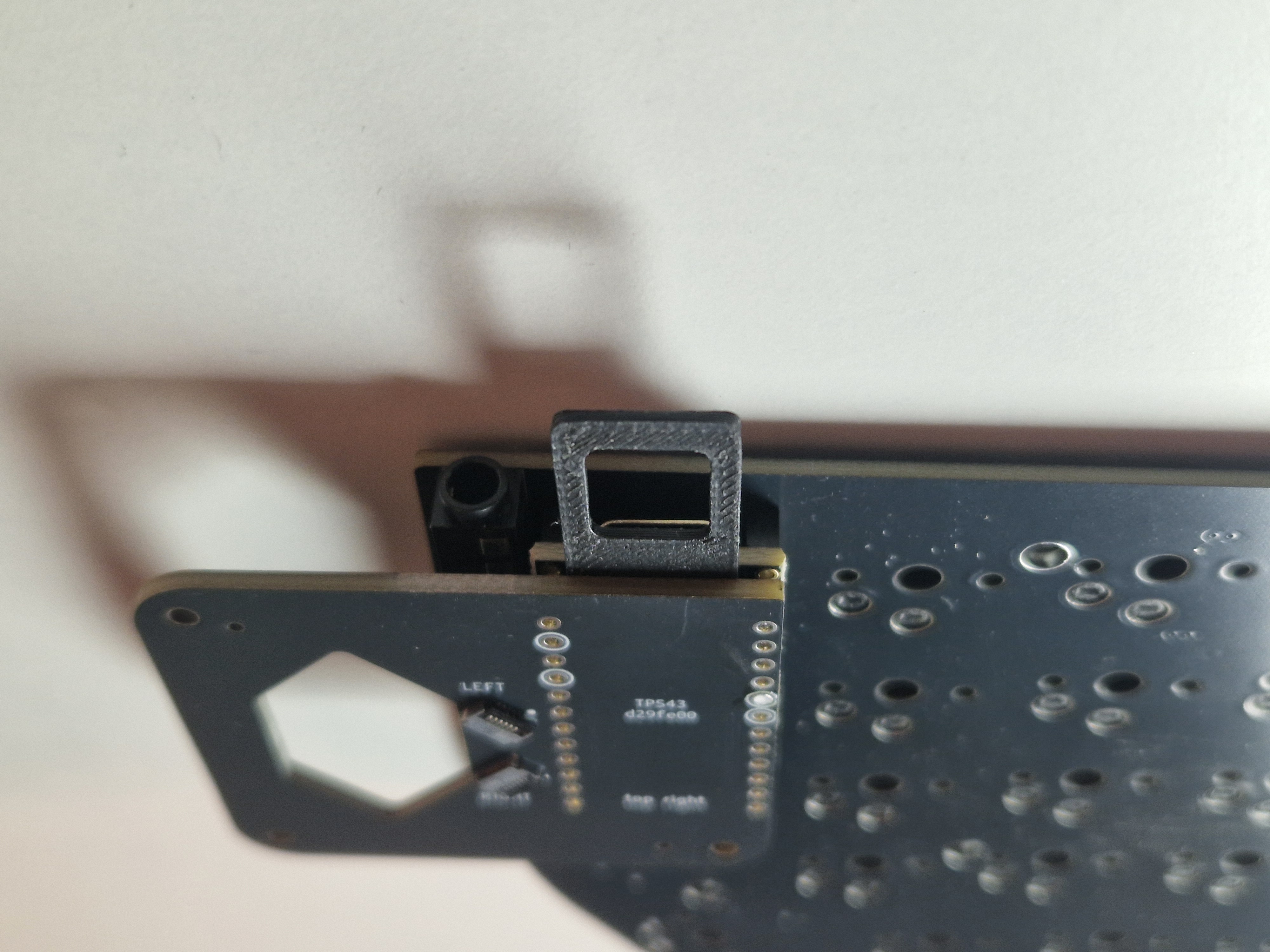
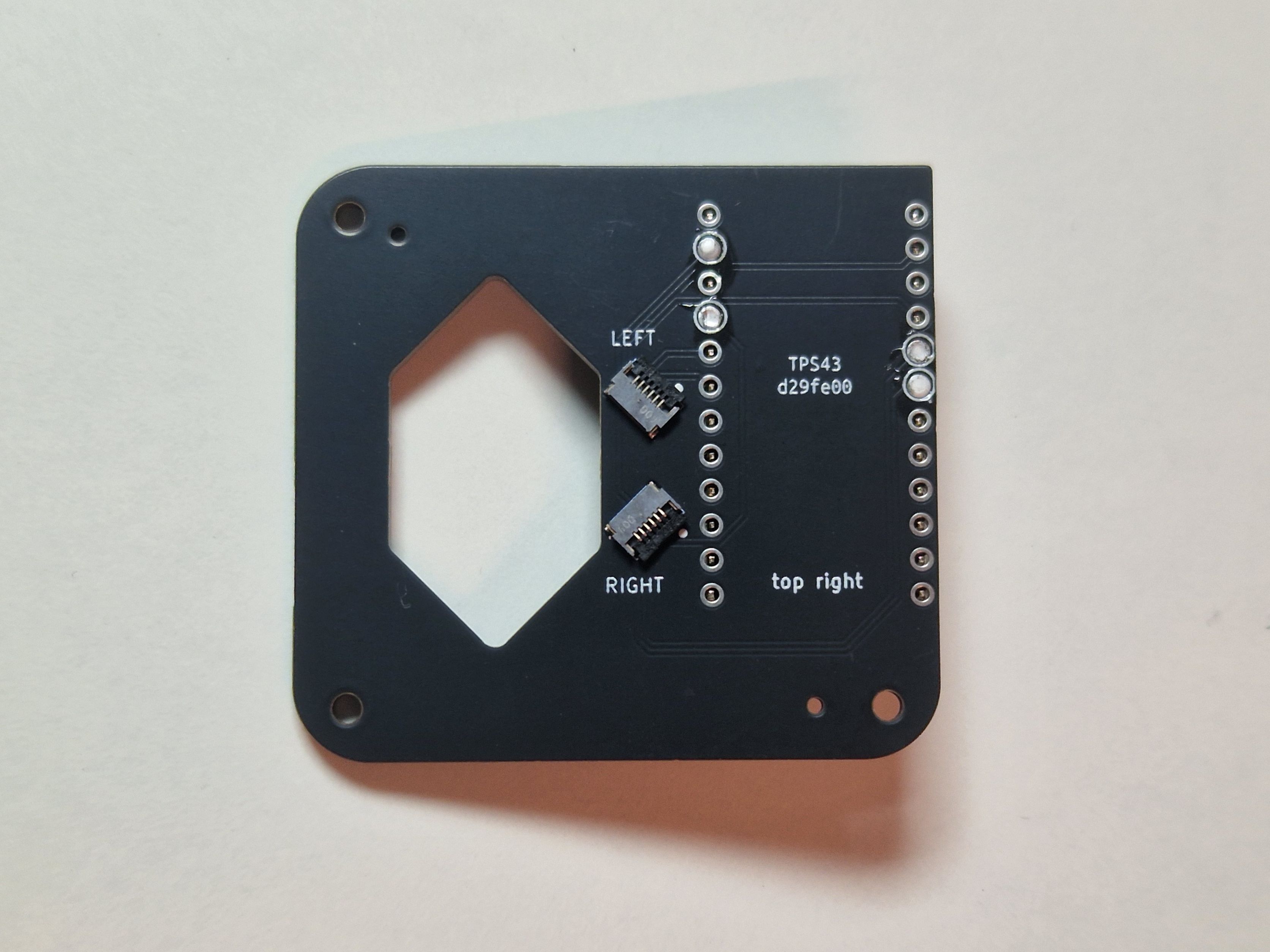
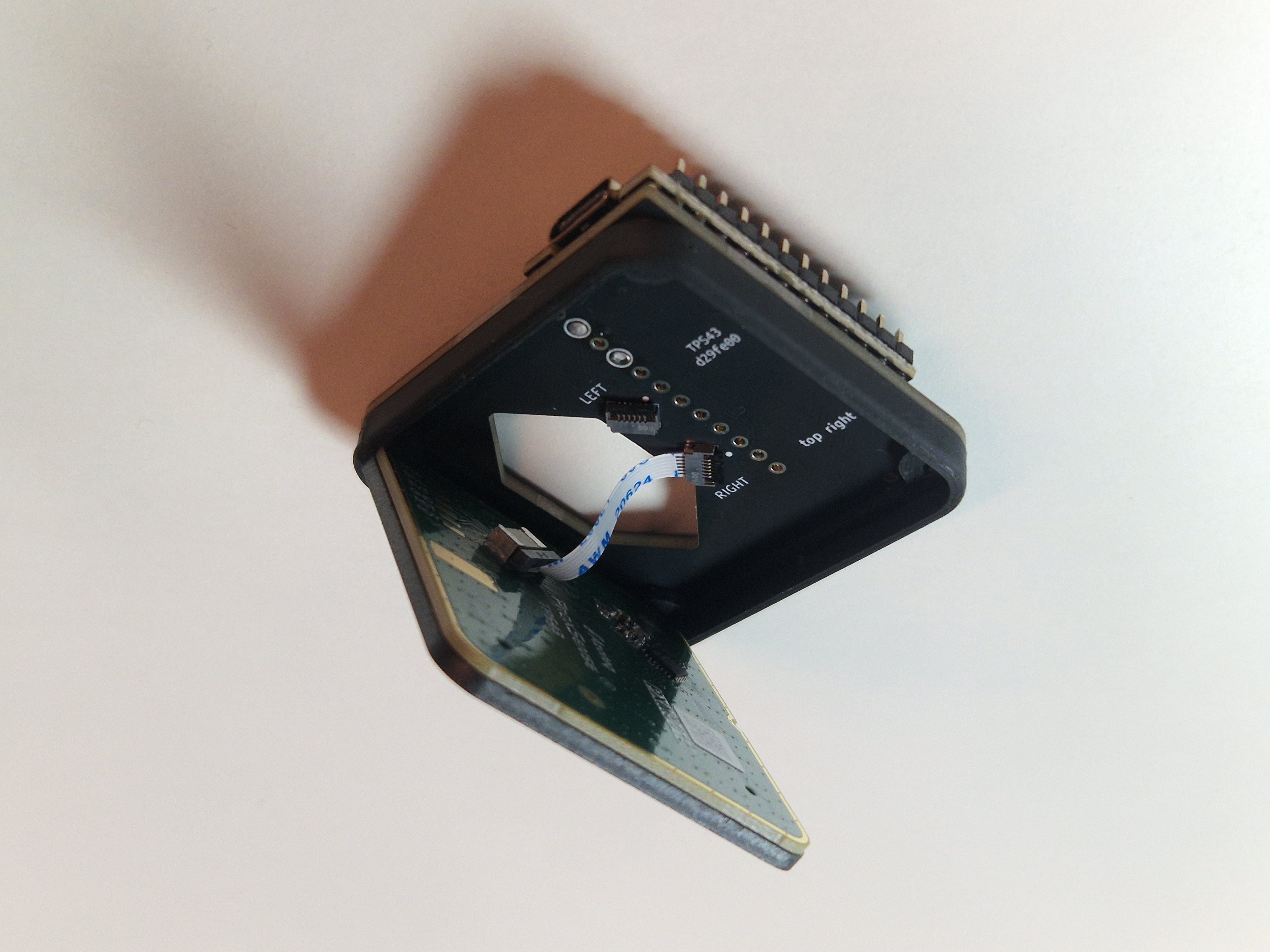
The adapter PCB is reversible: for a right sided setup, you should see "top right" on the top side of the adapter PCB (as seen below). Turn it upside down if you don't. In the pictures below the FFC connectors are on the "top right" side, but the current version of the PCB has them on the other side.
Put the 1mm spacer on your controller, and the adapter PCB on top. This ensures the adapter sits at a consistent distance from the controller. Check that it sits straight: if it's not straight, check if you have blobs of solder on the controller headers. If this is indeed the problem, reflow or remove solder until it sits flush on the spacer.
WARNING
Make sure the through holes on the adapter are correctly lined up with the controller headers!
Proceed by soldering one of the circled holes:
Step 3
Check for flatness:
Finish soldering all 4, but avoid overdoing it resulting in a ball of solder that would later interfere with the printed mount.
Pull the spacer out.
Soldering part done! 👏
Assembly
INFO
Your kit may have the touchpad sandwiched with the top surface, already inside the printed mount. Skip these steps below.
Step 1
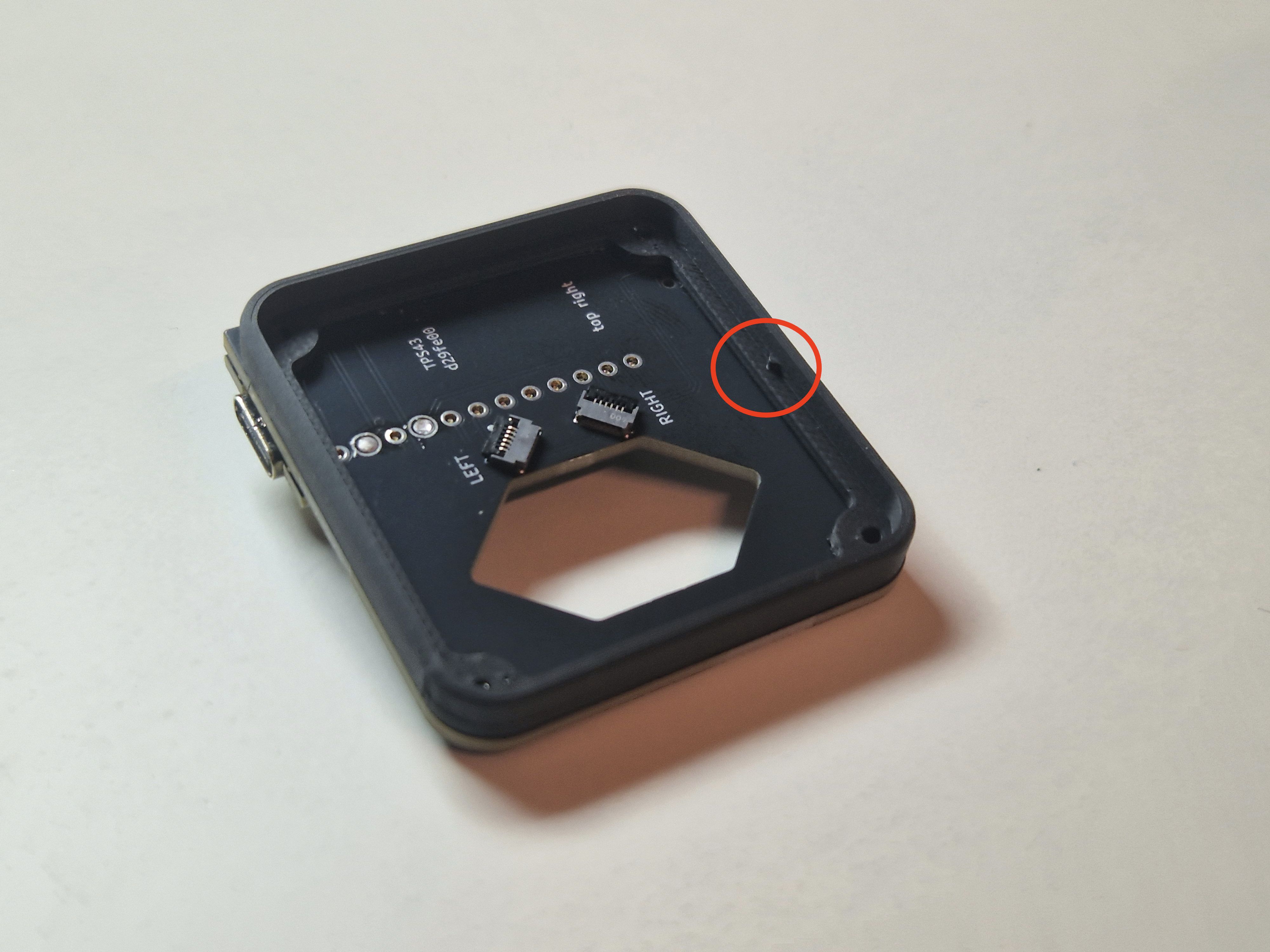
Next, we're going to fix the touchpad mount to the adapter PCB. The mount has a little notch on one of its internal sides.
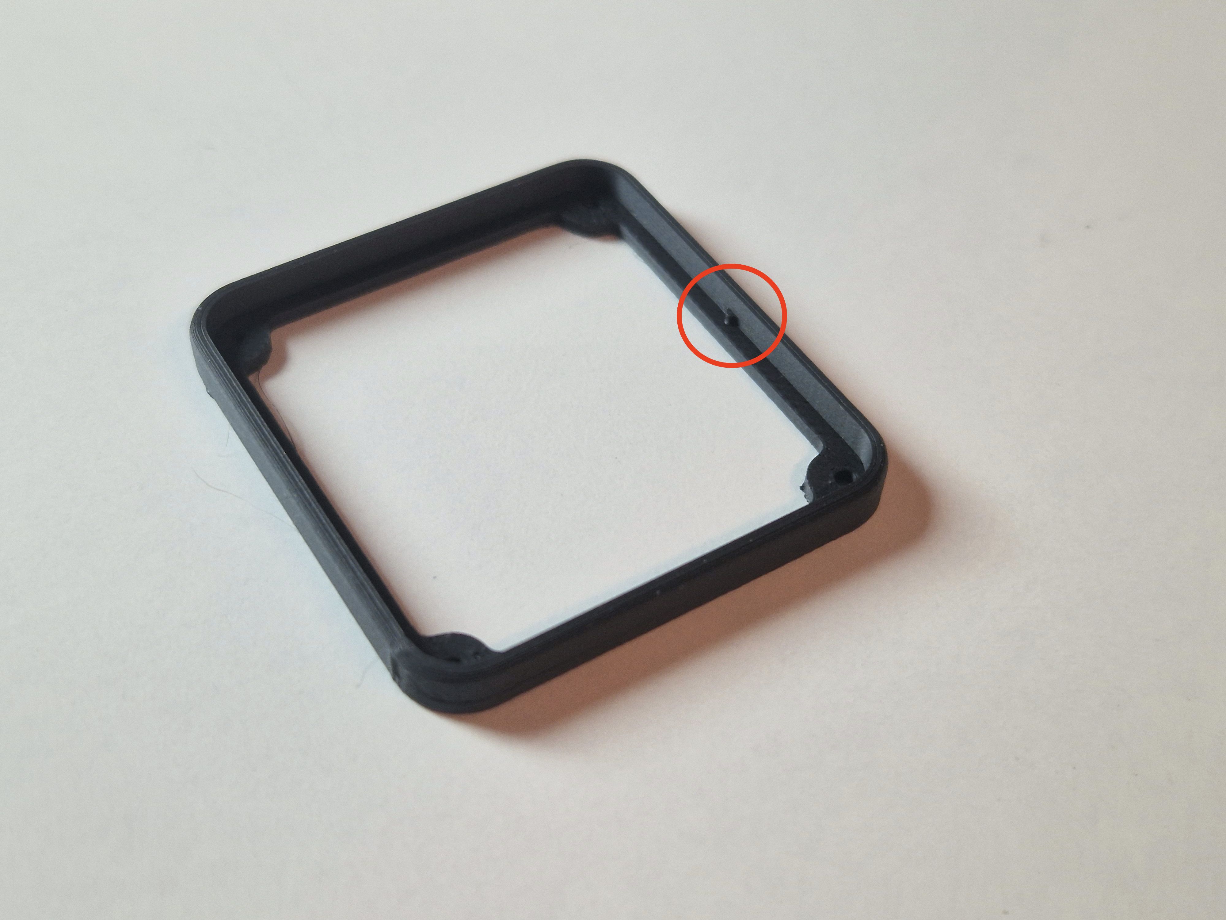
For a right sided touchpad, the notch should be on the south side of the adapter PCB. And for a left sided, on the the north side. In the pictures below, we have it on the south side for a right sided setup.
Remove the controller from the sockets, and using the M2 screws and spring washers, screw the two together (only two holes are necessary).
Step 2
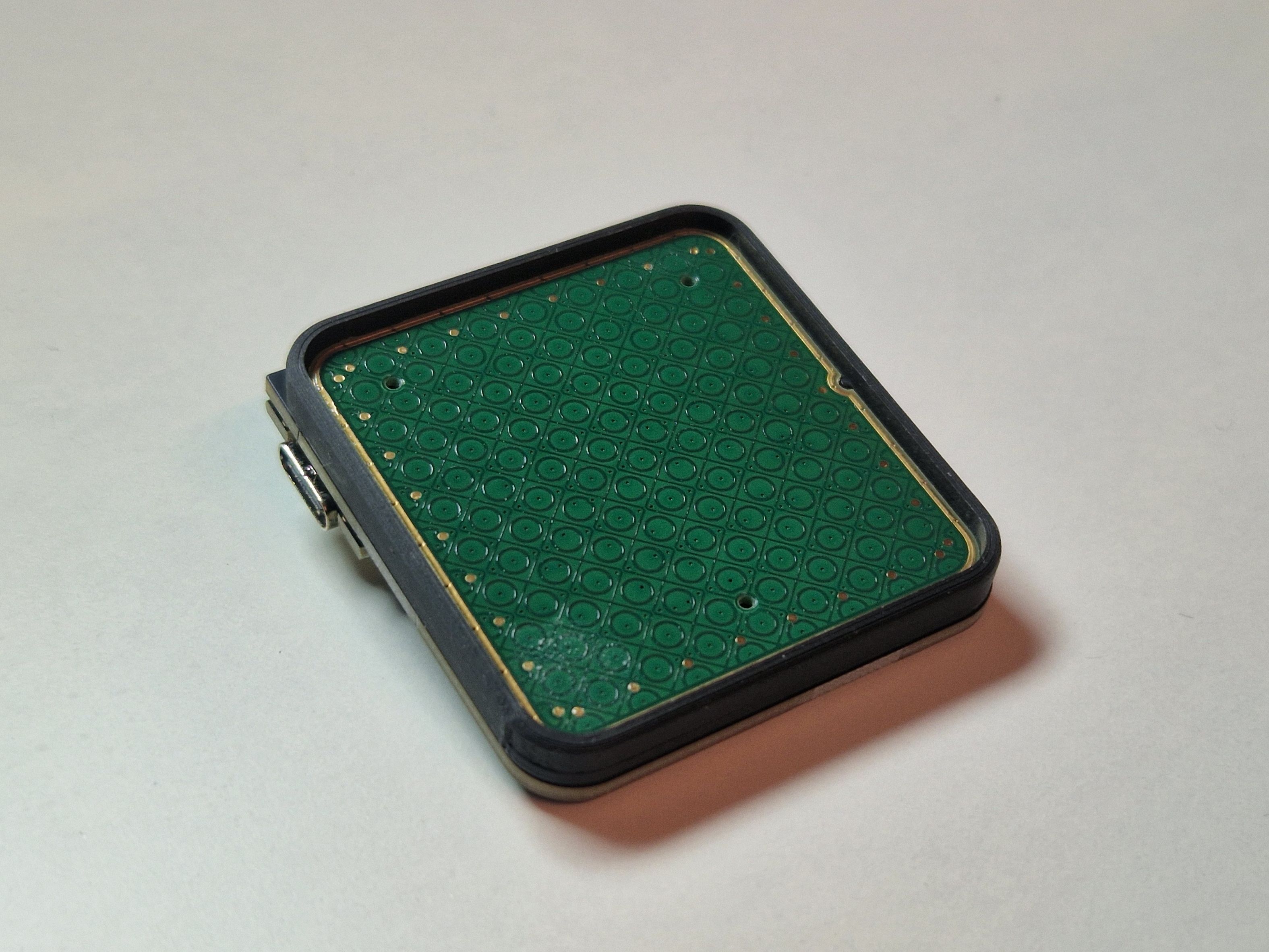
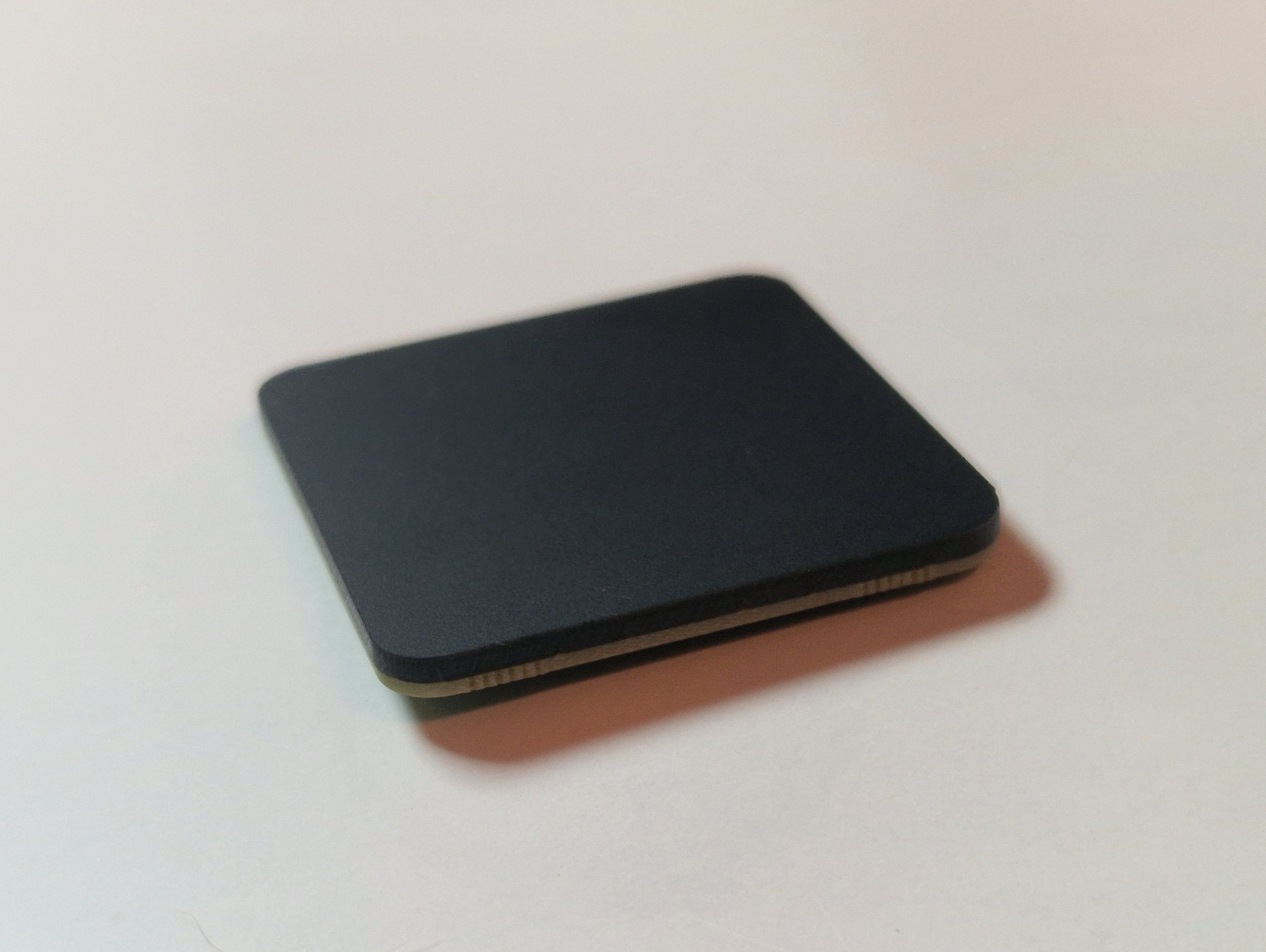
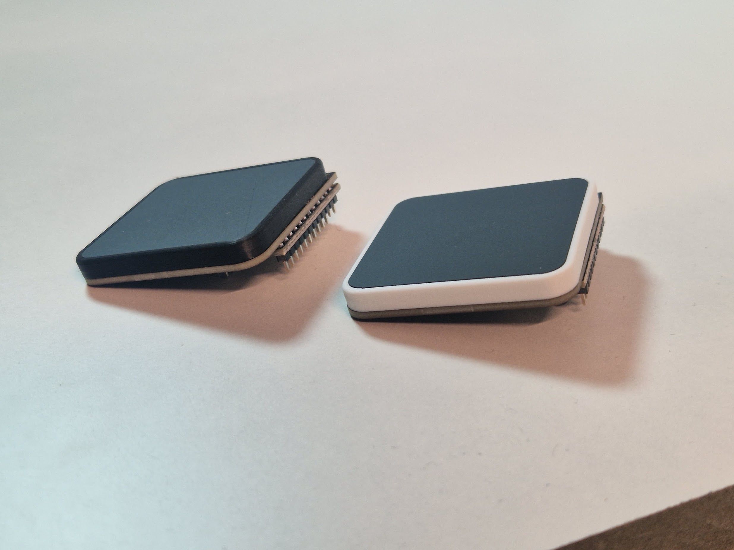
We're going to fix the touchpad top cover to the touchpad PCB. The cover is a 2mm acrylic piece that's one side matte, one side glossy. The matte side is smooth to the touch and is going to be the surface of the touchpad.
Start by positioning the touchpad inside the mount, aligning the notches:
Step 3
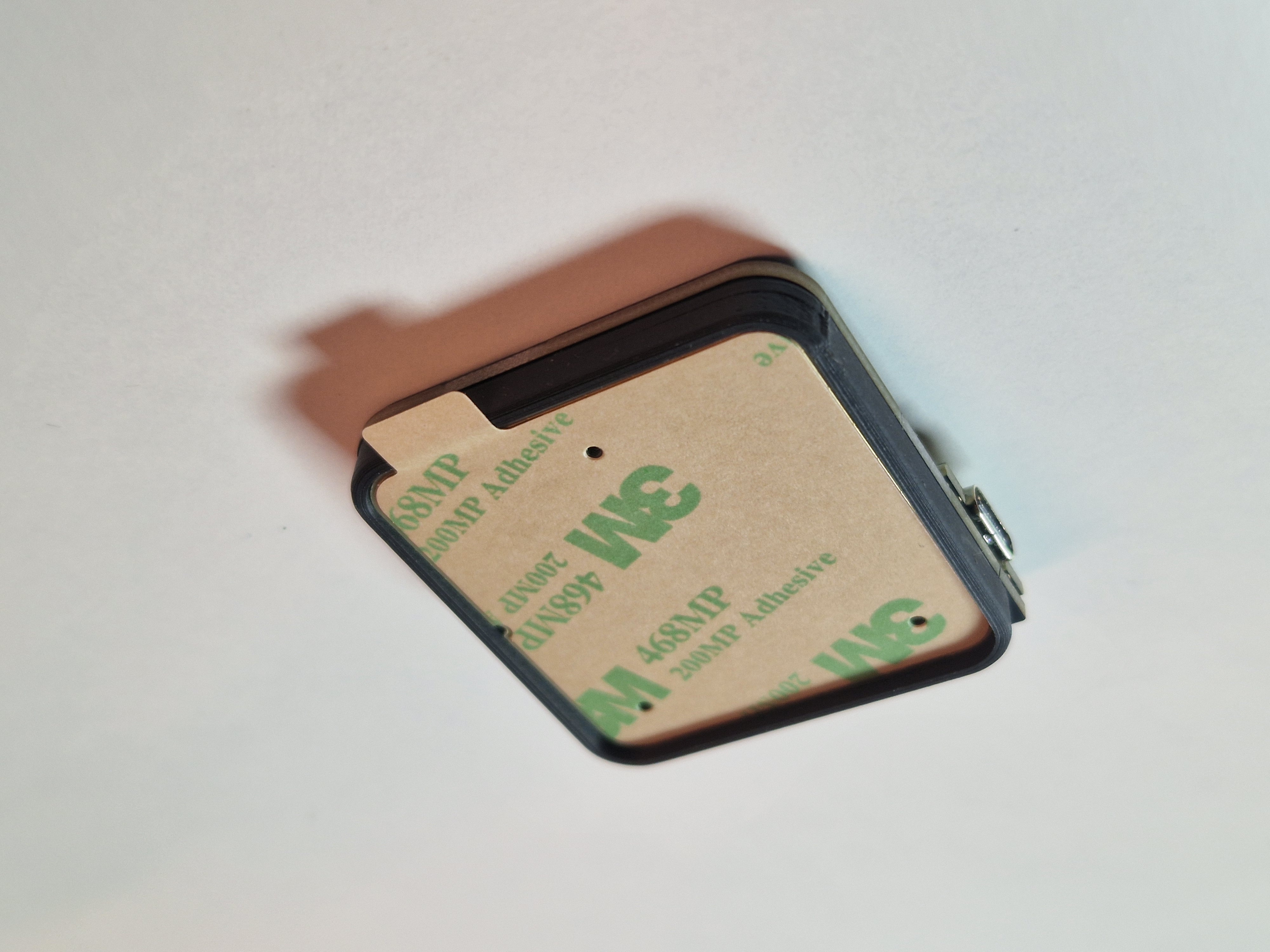
Remove the protective film off the cover and touchpad, exposing the sticky side of the touchpad.
Press the cover into the mount, matte side up, adhereing it to the touchpad. The cover is a press fit into the mount and should end up flush. Use parallel pliers if you can't do the last corner with your fingers.
DANGER
Once the cover is on the touchpad, it's basically impossible to separate the two. Make sure it's aligned properly!
Step 4
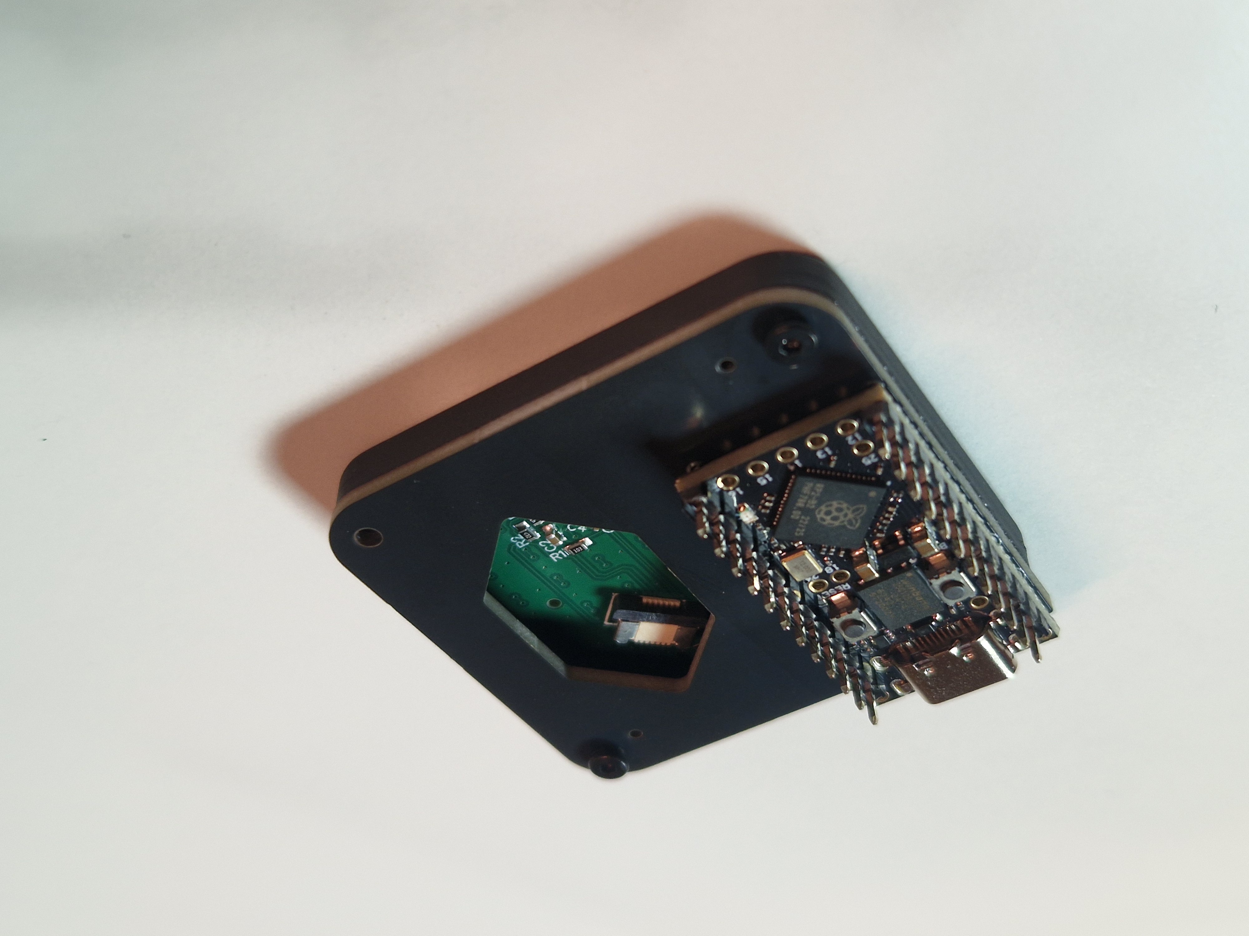
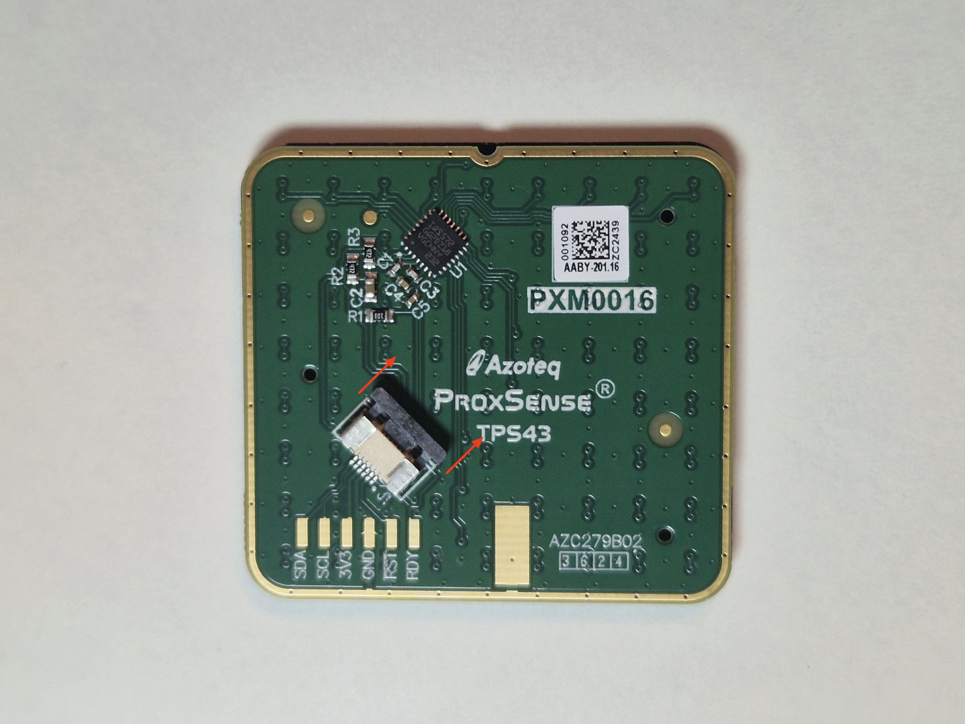
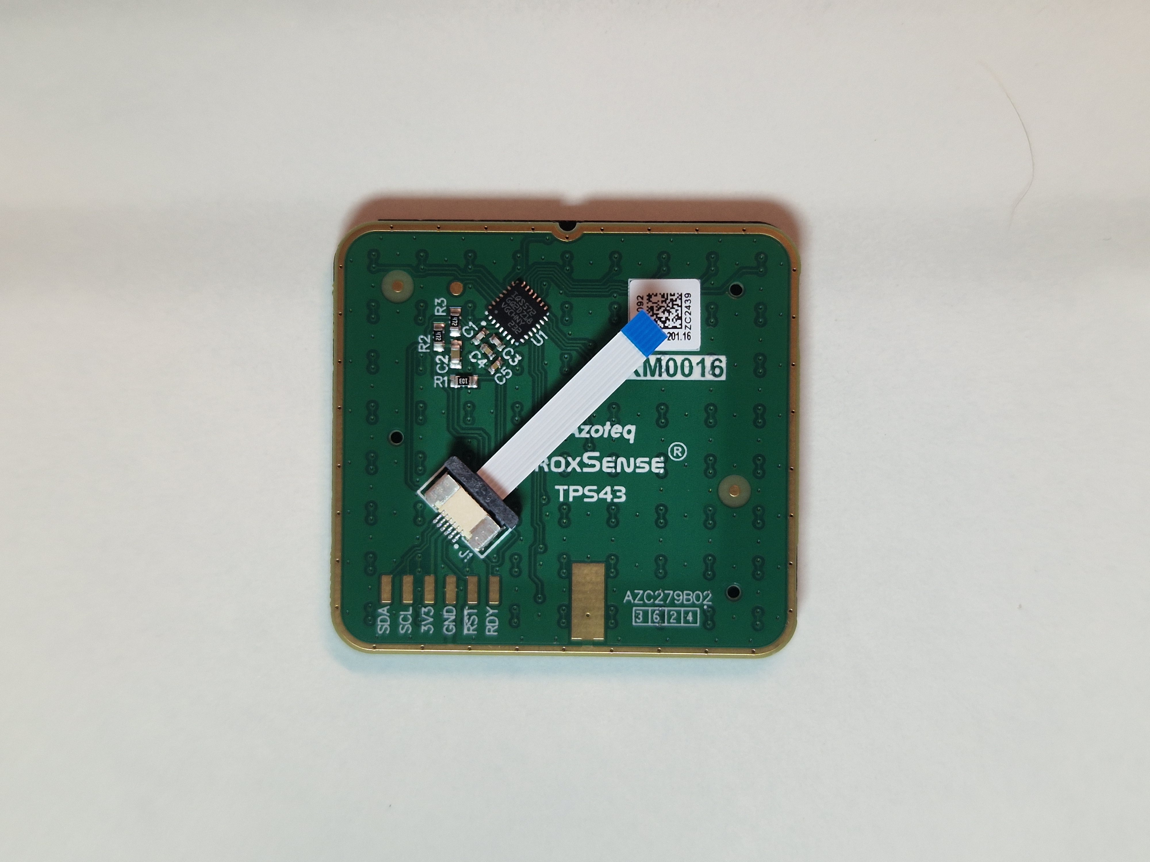
In this last step, we're going to connect the touchpad to the connector on the adapter PCB. Remove the touchpad (together with the cover) from the mount and open the connector on the touchpad's bottom side by pulling it out.
Push the cable into the connector (with the blue stiffener on top), and close it.
Connect the other side of the cable to the connector on the adapter PCB. It might help to use tweezers or needle nose pliers to push it in.
Step 5
Push the touchpad back into the mount.
Step 6
Done! Head over to Firmware to flash the controller with touchpad support.
Firmware
The precompiled firmware is the easiest way to enable the touchpad on your keyboard.
If you'd like to code it yourself for some reason, see QMK docs.
Troubleshooting
- Ensure your firmware enables the touchpad.
- Ensure all 4 solder joints on the adapter PCB are making a connection to the controller.
- Ensure the FFC cable is connected correctly:
- Is the cable oriented correctly?
- Do the cable contacts all look good?
Still having issues? Reach out to support.